AUTOMATIC TRANSMISSION SYSTEM Pattern Select Switch Snow Mode Circuit
DESCRIPTION
When SNOW is selected, the operation of the throttle motor is moderated to control engine output. This helps to reduce skidding of the drive wheels, and assists with takeoff acceleration, driving straightness and turning stability.
WIRING DIAGRAM
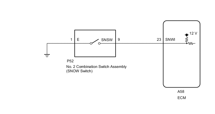
PROCEDURE
-
INSPECT NO. 2 COMBINATION SWITCH ASSEMBLY
-
Inspect the No. 2 combination switch assembly.
Result Proceed to OK NG
NG 
REPLACE NO. 2 COMBINATION SWITCH ASSEMBLY Click here
OK 
-
-
CHECK HARNESS AND CONNECTOR (NO. 2 COMBINATION SWITCH ASSEMBLY - BODY GROUND)
-
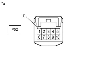
*a Front view of wire harness connector
(to No. 2 Combination Switch Assembly)
Disconnect the combination switch assembly connector.
-
Measure the resistance according to the value(s) in the table below.
Standard Resistance Tester Connection Condition Specified Condition P52-1 (E) - Body ground Always Below 1 Ω Result Proceed to OK NG
NG
REPAIR OR REPLACE HARNESS OR CONNECTOR
OK
-
-
CHECK HARNESS AND CONNECTOR (NO. 2 COMBINATION SWITCH ASSEMBLY - ECM)
-
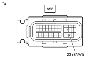
*a Front view of wire harness connector
(to ECM)
Disconnect the ECM connector.
-
Measure the resistance according to the value(s) in the table below.
Standard Resistance Tester Connection Switch Condition Specified Condition A58-23 (SNWI) - Body ground No. 2 combination switch assembly knob turned and held at SNOW position Below 10 Ω A58-23 (SNWI) - Body ground No. 2 combination switch assembly knob not turned to SNOW position 10 kΩ or higher Result Proceed to OK NG
OK
PROCEED TO NEXT SUSPECTED AREA SHOWN IN PROBLEM SYMPTOMS TABLE Click here
NG
REPAIR OR REPLACE HARNESS OR CONNECTOR
-