AUTOMATIC TRANSMISSION SYSTEM Shift Paddle Switch Circuit
DESCRIPTION
When the shift state is in drive (D), operating the "-" side shift paddle switch will cause the transmission to enter fixed range mode which restricts the highest gear. By operating the "+" (up-shift) or "-" (down-shift) shift paddle switch, the gear can be changed.
When the vehicle is being driven with the shift state in drive (D) (fixed range mode), if the vehicle is stopped or the accelerator pedal is kept steady for a certain period of time with the transmission in the same gear, the vehicle will change back automatically to normal D position operation.
When the shift state is in manual (M), it is possible to make use of the highest engine speeds by holding the vehicle in a gear. Gear hold control means that gear shifts will not be performed as long as the "+" (up-shift), or "-" (down-shift) shift paddle switch is not operated.
WIRING DIAGRAM
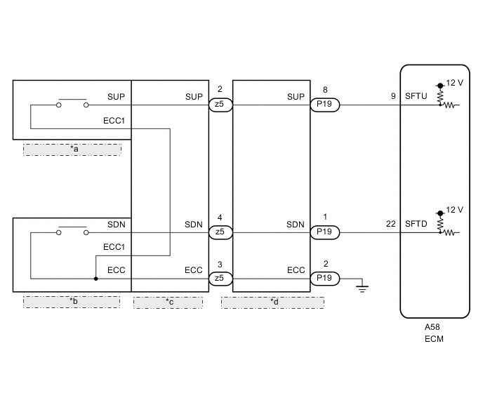
| *a | Shift Paddle Switch RH (Transmission Shift Switch Assembly) |
| *b | Shift Paddle Switch LH (Transmission Shift Switch Assembly) |
| *c | No. 2 Switch Wire |
| *d | Spiral Cable with Sensor Sub-assembly |
CAUTION / NOTICE / HINT
CAUTION:
The vehicle is equipped with a Supplemental Restraint System (SRS) which includes components such as airbags. Before servicing (including removal or installation of parts), be sure to read the precaution for Supplemental Restraint System.
PROCEDURE
-
READ VALUE USING GTS (SPORT SHIFT UP SW AND SPORT SHIFT DOWN SW)
-
Connect the GTS to the DLC3.
-
Turn the engine switch on (IG).
-
Turn the GTS on.
-
Enter the following menus: Powertrain / Engine / Data List.
-
According to the display on the GTS, read the Data List.
Powertrain > Engine > Data ListTester Display Measurement Item Range Normal Condition Diagnostic Note Sports Shift Up SW Sport shift up switch status ON or OFF
-
ON: "+" shift paddle operated (up-shift)
-
OFF: "+" shift paddle not operated (up-shift)
- Sports Shift Down SW Sport shift down switch status ON or OFF
-
ON: "-" shift paddle operated (down-shift)
-
OFF: "-" shift paddle not operated (down-shift)
-
Powertrain > Engine > Data ListTester Display Sports Shift Up SW Sports Shift Down SW Tech Tips
If the Data List updates slowly, perform measurement after selecting only the "Sports Shift Up SW" and "Sports Shift Down SW" items.
Result Result Proceed to Data display is within Normal Condition range A Data display is not within Normal Condition range B -
A 
PROCEED TO NEXT SUSPECTED AREA SHOWN IN PROBLEM SYMPTOMS TABLE Click here
B 
-
-
CHECK HARNESS AND CONNECTOR (SHIFT PADDLE SWITCH - ECM)
-
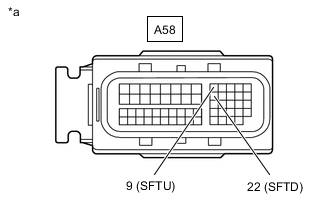
*a Front view of wire harness connector
(to ECM)
Disconnect the ECM connector.
-
Measure the resistance according to the value(s) in the table below.
Standard Resistance Tester Connection Condition Specified Condition A58-9 (SFTU) - Body ground "+" shift paddle operated (up-shift) Below 2.5 Ω A58-22 (SFTD) - Body ground "-" shift paddle operated (down-shift) Below 2.5 Ω A58-9 (SFTU) - Body ground "+" shift paddle not operated (up-shift) 1 MΩ or higher A58-22 (SFTD) - Body ground "-" shift paddle not operated (down-shift) 1 MΩ or higher Result Proceed to OK NG
OK
PROCEED TO NEXT SUSPECTED AREA SHOWN IN PROBLEM SYMPTOMS TABLE Click here
NG
-
-
CHECK HARNESS AND CONNECTOR (SPIRAL CABLE WITH SENSOR SUB-ASSEMBLY - BODY GROUND)
-
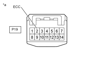
*a Front view of wire harness connector
(to Spiral Cable with Sensor Sub-assembly)
Disconnect the spiral cable with sensor sub-assembly connector.
-
Measure the resistance according to the value(s) in the table below.
Standard Resistance Tester Connection Condition Specified Condition P19-2 (ECC) - Body ground Always Below 1 Ω Result Proceed to OK NG
NG
REPAIR OR REPLACE HARNESS OR CONNECTOR
OK
-
-
CHECK HARNESS AND CONNECTOR (SPIRAL CABLE SUB-ASSEMBLY - ECM)
-
Disconnect the P19 spiral cable sub-assembly connector.
-
Disconnect the A58 ECM connector.
-
Measure the resistance according to the value(s) in the table below.
Standard Resistance Tester Connection Condition Specified Condition P19-8 (SUP) - A58-9 (SFTU) Always Below 1 Ω P19-1 (SDN) - A58-22 (SFTD) Always Below 1 Ω P19-8 (SUP) or A58-9 (SFTU) - Body ground Always 10 kΩ or higher P19-1 (SDN) or A58-22 (SFTD) - Body ground Always 10 kΩ or higher Result Proceed to OK NG
NG
REPAIR OR REPLACE HARNESS OR CONNECTOR
OK
-
-
INSPECT SHIFT PADDLE SWITCH (TRANSMISSION SHIFT SWITCH ASSEMBLY)
-
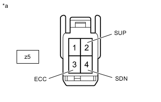
*a No. 2 Switch Wire
(to Spiral Cable with Sensor Sub-assembly)
Disconnect the No. 2 switch wire connector.
-
Measure the resistance according to the value(s) in the table below.
Standard Resistance Tester Connection Condition Specified Condition z5-2 (SUP) - z5-3 (ECC) "+" shift paddle operated (up-shift) Below 2.5 Ω z5-4 (SDN) - z5-3 (ECC) "-" shift paddle operated (down-shift) Below 2.5 Ω z5-2 (SUP) - z5-3 (ECC) "+" shift paddle not operated (up-shift) 1 MΩ or higher z5-4 (SDN) - z5-3 (ECC) "-" shift paddle not operated (down-shift) 1 MΩ or higher Result Proceed to OK NG
NG 
INSPECT SHIFT PADDLE SWITCH RH (TRANSMISSION SHIFT SWITCH ASSEMBLY) Click here
OK
-
-
INSPECT SPIRAL CABLE WITH SENSOR SUB-ASSEMBLY
-
Inspect the spiral cable with sensor sub-assembly.
Result Proceed to OK NG
OK
PROCEED TO NEXT SUSPECTED AREA SHOWN IN PROBLEM SYMPTOMS TABLE Click here
NG
REPLACE SPIRAL CABLE WITH SENSOR SUB-ASSEMBLY Click here
-
-
INSPECT SHIFT PADDLE SWITCH RH (TRANSMISSION SHIFT SWITCH ASSEMBLY)
-
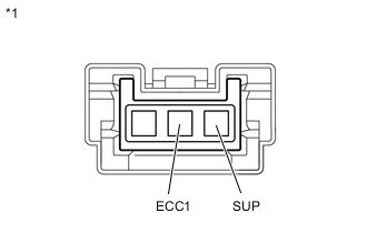
*1 Shift Paddle Switch RH (Transmission Shift Switch Assembly) Remove the shift paddle switch RH.
-
Measure the resistance according to the value(s) in the table below.
Standard Resistance Tester Connection Condition Specified Condition SUP - ECC1 "+" shift paddle operated (up-shift) Below 2.5 Ω SUP - ECC1 "+" shift paddle not operated (up-shift) 1 MΩ or higher Result Proceed to OK NG
NG
REPLACE SHIFT PADDLE SWITCH RH (TRANSMISSION SHIFT SWITCH ASSEMBLY) Click here
OK
-
-
INSPECT SHIFT PADDLE SWITCH LH (TRANSMISSION SHIFT SWITCH ASSEMBLY)
-
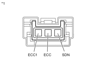
*a Shift Paddle Switch LH (Transmission Shift Switch Assembly) Remove the shift paddle switch LH.
-
Measure the resistance according to the value(s) in the table below.
Standard Resistance Tester Connection Condition Specified Condition SDN - ECC "-" shift paddle operated (down-shift) Below 2.5 Ω SDN - ECC1 "-" shift paddle operated (down-shift) Below 2.5 Ω SDN - ECC "-" shift paddle not operated (down-shift) 1 MΩ or higher SDN - ECC1 "-" shift paddle not operated (down-shift) 1 MΩ or higher Result Proceed to OK NG
OK
REPLACE NO. 2 SWITCH WIRE Click here
NG
REPLACE SHIFT PADDLE SWITCH LH (TRANSMISSION SHIFT SWITCH ASSEMBLY) Click here
-