ELECTRONIC SHIFT LEVER SYSTEM TERMINALS OF ECU
-
CHECK SHIFT CONTROL ECU
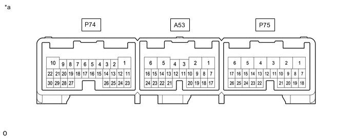
*a TERMINALS OF SHIFT CONTROL ECU - - Terminal No. (Symbol) Input/Output Wiring Color Terminal Description Condition Specified Condition A53-1 (MWA) - P75-6 (E01) Output L - W-B Parking lock motor signal Engine switch on (IG) 7.5 to 15.4 V A53-2 (MVA) - P75-6 (E01) Output R - W-B Parking lock motor signal Engine switch on (IG) 7.5 to 15.4 V A53-5 (MUA) - P75-6 (E01) Output B - W-B Parking lock motor signal Engine switch on (IG) 7.5 to 15.4 V A53-7 (SS) - Body ground - - shield line Always Below 1 Ω A53-12 (BMA1) - P74-1 (E1) Output G - W-B P CON MTR relay operation signal Engine switch off → Engine switch on (IG) 7.5 to 15.4 V → Below 1 V A53-16 (RS) - Body ground - - shield line Always Below 1 Ω A53-17 (E2NS) - P74-1 (E1) Input G - W-B Range sensor ground Always 0.4 V or less A53-18 (NS2) - A53-17 (E2NS) Input R - G Range sensor signal Engine switch on (IG), shift state park (P) 0.5 to 4.5 V A53-19 (VCNS) - A53-17 (E2NS) Output B - G Power source of range sensor Engine switch on (IG) 4.5 to 5.5 V A53-20 (NS1) - A53-17 (E2NS) Input W - G Range sensor signal Engine switch on (IG), shift state park (P) 0.5 to 4.5 V A53-21 (RB) - A53-24 (E2) Input R - G Rotation angle sensor signal Engine switch off → Engine switch on (IG) 0.4 V or less → 4.9 V or higher Engine switch on (IG), changing the shift state between park (P) and neutral (N) Pulse generation (see waveform 1) A53-22 (VC) - A53-24 (E2) Output W - G Power source of rotation angle sensor Engine switch on (IG) 4.5 to 5.5 V A53-23 (RA) - A53-24 (E2) Input B - G Rotation angle sensor signal Engine switch off → Engine switch on (IG) 0.4 V or less → 4.9 V or higher Engine switch on (IG), changing the shift state between park (P) and neutral (N) Pulse generation (see waveform 1) A53-24 (E2) - P74-1 (E1) Output G - W-B Rotation angle sensor ground Always 0.4 V or less P74-1 (E1) - Body ground - W-B - - Ground Always Below 1 Ω P74-3 (SBFS) - P74-1 (E1) Output BE - W-B Fail-safe signal Engine switch on (IG) Pulse generation (see waveform 2) P74-5 (CA2L) - P74-1 (E1) Input/Output W - W-B CAN communication signal Engine switch on (IG) Pulse generation (see waveform 3) P74-6 (CA2H) - P74-1 (E1) Input/Output R - W-B CAN communication signal Engine switch on (IG) Pulse generation (see waveform 3) P74-8 (CA1L) - P74-1 (E1) Input/Output W - W-B CAN communication signal Engine switch on (IG) Pulse generation (see waveform 4) P74-9 (CA1H) - P74-1 (E1) Input/Output Y - W-B CAN communication signal Engine switch on (IG) Pulse generation (see waveform 4) P74-10 (BUB) - P74-1 (E1) Input G - W-B Sub-battery power supply Engine switch on (IG)*1 8 to 15.4 V P74-11 (EC) - Body ground - W-B - - Ground Always Below 1 Ω P74-13 (PPOS) - P74-1 (E1) Output LG - W-B Shift state signal Engine switch on (IG), shift state park (P) Pulse generation (see waveform 5) P74-15 (BL) - P74-1 (E1) Output R - W-B Back-up light relay operation signal Shift state reverse (R) 7.25 to 14.65 V Shift state not reverse (R) 1 V or less P74-18 (ACC) - P74-1 (E1) Input GR - W-B ACC power supply Engine switch on (ACC) 6 V or higher P74-22 (BUBI) - P74-1 (E1) Input P - W-B Sub-battery condition signal Engine switch on (IG) Pulse generation (see waveform 6) P74-24 (BMA2) - P74-1 (E1) Output V - W-B P CON MTR2 relay operation signal Engine switch on (IG)*2 7.5 to 15.4 V P74-27 (IG2) - P74-1 (E1) Input B - W-B IG2 power supply Engine switch on (IG) 6 V or higher P74-29 (BUBO) - P74-1 (E1) Output L - W-B Backup request signal Engine switch on (IG) Pulse generation (see waveform 7) P75-1 (BATT) - P74-1 (E1) Input G - W-B Battery power supply Always 8 to 15.4 V P75-4 (E03) - Body ground - W-B - - Ground Always Below 1 Ω P75-5 (E02) - Body ground - W-B - - Ground Always Below 1 Ω P75-6 (E01) - Body ground - W-B - - Ground Always Below 1 Ω P75-10 (P1) - P74-1 (E1) Input SB - W-B P position switch signal Engine switch on (IG), P position switch not operated 5.8 V or higher Engine switch on (IG), P position switch being pushed and held 2.47 to 5.8 V P75-11 (ACCI) - P74-1 (E1) Output P - W-B Power source of shift position indicator Engine switch off → Engine switch on (ACC) 1 V or less → 8 to 15.4 V P75-12 (INDP) - P74-1 (E1) Output B - W-B Shift position indicator signal (P) Shift state park (P) 1 V or less Shift state not park (P) 8 to 15.4 V P75-13 (INDM) - P74-1 (E1) Output Y - W-B Shift position indicator signal (M) Shift state manual (M) 1 V or less Shift state not manual (M) 8 to 15.4 V P75-14 (INDD) - P74-1 (E1) Output R - W-B Shift position indicator signal (D) Shift state drive (D) 1 V or less Shift state not drive (D) 8 to 15.4 V P75-15 (INDN) - P74-1 (E1) Output G - W-B Shift position indicator signal (N) Shift state neutral (N) 1 V or less Shift state not neutral (N) 8 to 15.4 V P75-16 (INDR) - P74-1 (E1) Output BE - W-B Shift position indicator signal (R) Shift state reverse (R) 1 V or less Shift state not reverse (R) 8 to 15.4 V P75-17 (E12) - Body ground - W-B - - Ground Always Below 1 Ω P75-18 (STP) - P74-1 (E1) Input R - W-B Stop light switch signal Brake pedal depressed 7.17 V or higher Brake pedal released 2 V or less P75-19 (VSI1) - P75-24 (E2X1) Input B - LG Shift lever position signal Engine switch on (IG), shift lever in home position 3.634 to 4.226 V Engine switch on (IG), shift lever in D 1.366 to 1.923 V Engine switch on (IG), shift lever in N 0.774 to 1.366 V Engine switch on (IG), shift lever in R 0.3 to 0.774 V Engine switch on (IG), shift lever in M 2.5 to 3.634 V P75-20 (VCX1) - P75-24 (E2X1) Output L - LG Power source of shift lever position sensor Engine switch on (IG) 4.5 to 5.5 V P75-21 (VSI2) - P75-24 (E2X1) Input W - LG Shift lever position signal Engine switch on (IG), shift lever in home position 3.084 to 3.676 V Engine switch on (IG), shift lever in D 2.08 to 2.5 V Engine switch on (IG), shift lever in N 1.324 to 2.08 V Engine switch on (IG), shift lever in R 0.3 to 1.324 V Engine switch on (IG), shift lever in M 2.5 to 3.084 V P75-22 (VCX2) - P75-26 (E2X2) Output GR - SB Power source of shift lever position sensor Engine switch on (IG) 4.5 to 5.5 V P75-23 (VSI3) - P75-26 (E2X2) Input V - SB Shift lever position signal Engine switch on (IG), shift lever in home position 1.324 to 1.916 V Engine switch on (IG), shift lever in D 3.676 to 4.75 V Engine switch on (IG), shift lever in N 2.92 to 3.676 V Engine switch on (IG), shift lever in R 2.5 to 2.92 V Engine switch on (IG), shift lever in M 0.3 to 1.324 V P75-24 (E2X1) - P74-1 (E1) Input LG - W-B Shift lever position sensor ground Engine switch on (IG) 0.4 V or less P75-25 (VSI4) - P75-26 (E2X2) Input P - SB Shift lever position signal Engine switch on (IG), shift lever in home position 0.774 to 1.366 V Engine switch on (IG), shift lever in D 4.226 to 4.75 V Engine switch on (IG), shift lever in N 3.634 to 4.226 V Engine switch on (IG), shift lever in R 3.077 to 3.634 V Engine switch on (IG), shift lever in M 0.3 to 0.774 V P75-26 (E2X2) - P74-1 (E1) Input SB - W-B Shift lever position sensor ground Engine switch on (IG) 0.4 V or less *1: Power is supplied from the sub-battery module assembly for only 5 seconds after the engine switch is turned on (IG). Therefore, measure the voltage during that time.
*2: With the engine switch on (IG), disconnect the cable from the negative (-) battery terminal and check that the voltage level changes.
-
OSCILLOSCOPE WAVEFORMS
Tech Tips
Oscilloscope waveform samples are provided here for reference only. Noise and fluctuating waveforms have been omitted.
-
Waveform 1 (Rotation angle sensor signal)
Item Contents Terminal CH1: RA - E2
CH2: RB - E2
Equipment setting 2 V/DIV., 200 ms./DIV. Condition Engine switch on (IG), changing the shift state between park (P) and neutral (N) Tech Tips
When changing the shift state from park (P) to neutral (N), or neutral (N) to park (P) with the engine switch on (IG), a waveform will be generated for up to 1.5 seconds.
-

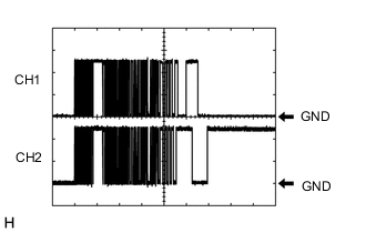
Waveform 2 (Fail-safe signal)
Item Contents Terminal SBFS - E1 Equipment setting 10 V/DIV., 20 ms./DIV. Condition Engine switch on (IG) Tech Tips
The waveforms differ when the shift control ECU is malfunctioning.
-
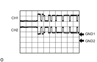
Waveform 3 (CAN communication signal)
Item Contents Terminal CH1: CA2H - E1
CH2: CA2L - E1
Equipment setting 1 V/DIV., 10 μs./DIV. Condition Engine switch on (IG) Tech Tips
The waveform will vary depending on the content of the digital communication (digital signal).
-
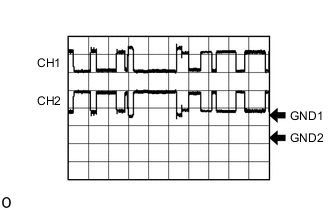
Waveform 4 (CAN communication signal)
Item Contents Terminal CH1: CA1H - E1
CH2: CA1L - E1
Equipment setting 1 V/DIV., 10 μs./DIV. Condition Engine switch on (IG) Tech Tips
The waveform will vary depending on the content of the digital communication (digital signal).
-
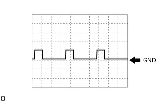
Waveform 5 (Shift state signal)
Item Contents Terminal PPOS - E1 Equipment setting 10 V/DIV., 10 ms./DIV. Condition Engine switch on (IG), shift state park (P) Tech Tips
The waveform will vary depending on the shift state.
-
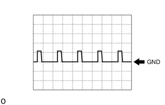
Waveform 6 (Sub-battery condition signal)
Item Contents Terminal BUBI - E1 Equipment setting 10 V/DIV., 10 ms./DIV. Condition Engine switch on (IG) Tech Tips
The duty ratio changes according to the vehicle condition.
-
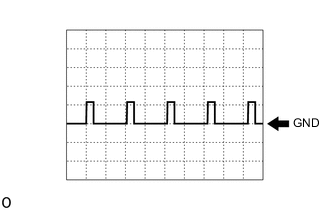
Waveform 7 (Backup request signal)
Item Contents Terminal BUBO - E1 Equipment setting 10 V/DIV., 10 ms./DIV. Condition Engine switch on (IG) Tech Tips
The duty ratio changes according to the vehicle condition.
-