METER / GAUGE SYSTEM, Diagnostic DTC:B1321
| DTC Code | DTC Name |
|---|---|
| B1321 | Lost Communication with EMV |
DESCRIPTION
| DTC No. | Detection Item | DTC Detection Condition | Trouble Area | Memory |
|---|---|---|---|---|
| B1321 | Lost Communication with EMV |
|
|
DTC stored |
WIRING DIAGRAM
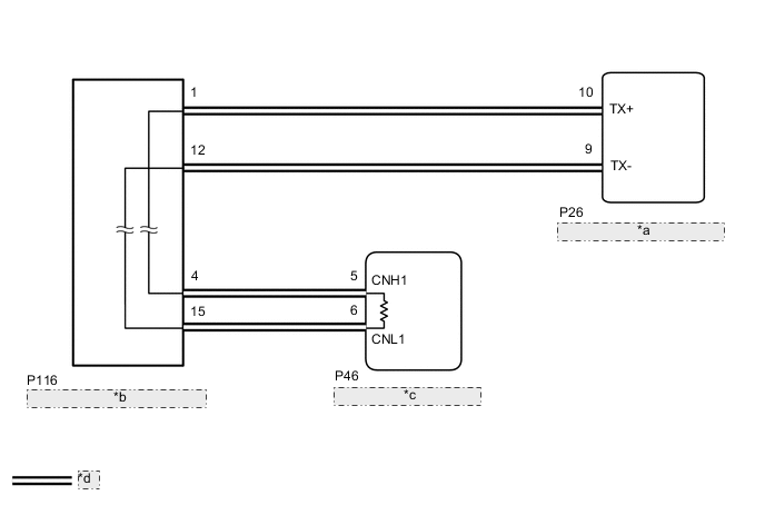
| *a | Combination Meter Assembly |
| *b | No. 4 CAN Junction Connector |
| *c | Radio Receiver Assembly |
| *d | Local Bus Communication Line |
CAUTION / NOTICE / HINT
Note
-
After turning the engine switch off, waiting time may be required before disconnecting the cable from the negative (-) battery terminal. Therefore, make sure to read the disconnecting the cable from the negative (-) battery terminal notices before proceeding with work.
-
When disconnecting the cable from the negative (-) battery terminal while performing repairs, some systems need to be initialized after the cable is reconnected.
-
When replacing the combination meter assembly, always replace it with a new one. If a combination meter assembly which was installed to another vehicle is used, the information stored in it will not match the information from the vehicle and a DTC may be stored.
-
The following malfunctions may occur if a radio receiver assembly from another vehicle is installed to this vehicle. Therefore, when replacing the radio receiver assembly, be sure to replace it with new one.
-
Communication malfunction DTC is output
-
Does not operate normally
Tech Tips
-
B1321 will not continue to output when clear DTC is performed even if the malfunction continues.
-
Depending on the parts that are replaced during vehicle inspection or maintenance, performing initialization, registration or calibration may be needed.
PROCEDURE
-
CHECK FOR DTC (NAVIGATION SYSTEM)
-
Check if navigation system DTCs are output.
Body Electrical > Navigation System > Trouble CodesResult Result Proceed to Navigation system DTCs are not output. A Navigation system DTCs are output. B
B 
GO TO NAVIGATION SYSTEM Click here
A 
-
-
CHECK HARNESS AND CONNECTOR (NO. 4 CAN JUNCTION CONNECTOR - RADIO RECEVER ASSEMBLY)
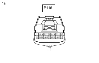
*a Rear view of wire harness connector
(to No. 4 CAN Junction Connector)
-
Disconnect the No. 4 CAN junction connector.
-
Measure the resistance according to the value(s) in the table below.
Standard Resistance Tester Connection Condition Specified Condition P116-4 - P116-15 Cable disconnected from negative (-) battery terminal 108 to 132 Ω Result Proceed to OK NG
NG 
CHECK HARNESS AND CONNECTOR (RADIO RECEVER ASSEMBLY - NO. 4 CAN JUNCTION CONNECTOR) Click here
OK
-
-
CHECK HARNESS AND CONNECTOR (NO. 4 CAN JUNCTION CONNECTOR - COMBINATION METER ASSEMBLY)
*a Rear view of wire harness connector
(to No. 4 CAN Junction Connector)
-
Measure the resistance according to the value(s) in the table below.
Standard Resistance Tester Connection Condition Specified Condition P116-1 - P116-12 Cable disconnected from negative (-) battery terminal 200 Ω or higher Result Proceed to OK NG
OK
REPLACE NO. 4 CAN JUNCTION CONNECTOR
NG
-
-
CHECK HARNESS AND CONNECTOR (NO. 4 CAN JUNCTION CONNECTOR - COMBINATION METER ASSEMBLY)
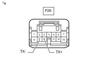
*a Front view of wire harness connector
(to Combination Meter Assembly Connector)
-
Disconnect the combination meter assembly connector.
-
Reconnect the P116 No. 4 CAN junction connector.
-
Measure the resistance according to the value(s) in the table below.
Standard Resistance Tester Connection Condition Specified Condition P26-10(TX+) - P26-9(TX-) Cable disconnected from negative (-) battery terminal 54 to 69 Ω Result Proceed to OK NG
OK
REPLACE COMBINATION METER ASSEMBLY Click here
NG
REPAIR OR REPLACE HARNESS OR CONNECTOR
-
-
CHECK HARNESS AND CONNECTOR (RADIO RECEVER ASSEMBLY - NO. 4 CAN JUNCTION CONNECTOR)
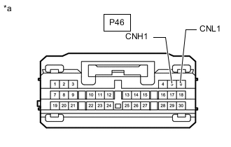
*a Front view of wire harness connector
(to Radio Recever Assembly Connector)
-
Disconnect the radio recever assembly connector.
-
Reconnect the P116 No. 4 CAN junction connector.
-
Measure the resistance according to the value(s) in the table below.
Standard Resistance Tester Connection Condition Specified Condition P46-5(CNH1) - P46-6(CNL1) Cable disconnected from negative (-) battery terminal 108 to 132 Ω Result Proceed to OK NG
OK
REPLACE RADIO RECEIVER ASSEMBLY Click here
NG
REPAIR OR REPLACE HARNESS OR CONNECTOR
-