METER / GAUGE SYSTEM, Diagnostic DTC:B1507, B1508
| DTC Code | DTC Name |
|---|---|
| B1507 | Open in Turn Signal Circuit |
| B1508 | Short in Turn Signal / Hazard Flasher Circuit |
DESCRIPTION
These DTCs are stored when the combination meter assembly detects an open in a turn signal light circuit, or a short in a turn signal light circuit or the hazard warning light circuit.
| DTC No. | Detection Item | DTC Detection Condition | Trouble Area | Memory | Note |
|---|---|---|---|---|---|
| B1507 | Open in Turn Signal Circuit | When IG voltage is 9.5 V or more and the following condition is detected:
|
|
DTC stored | - |
| B1508 | Short in Turn Signal / Hazard Flasher Circuit | When IG voltage is 9.5 V or more and the following condition is detected:
|
|
DTC stored | - |
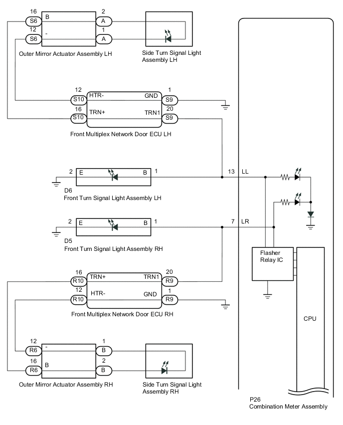
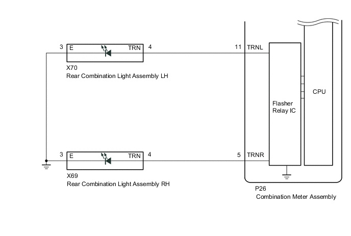
WIRING DIAGRAM
CAUTION / NOTICE / HINT
Note
-
Inspect the LEDs for this system before performing the following procedure.
-
When replacing the combination meter assembly, always replace it with a new one. If a combination meter assembly which was installed to another vehicle is used, the information stored in it will not match the information from the vehicle and a DTC may be stored.
PROCEDURE
-
INSPECT LIGHTS
-
Inspect the illumination of each turn signal light.
Result Result Proceed to RH side turn signal light does not illuminate. A LH side turn signal light does not illuminate. B
B 
CHECK TURN SIGNAL LIGHTS (LH SIDE) Click here
A 
-
-
CHECK TURN SIGNAL LIGHTS (RH SIDE)
-
Turn the engine switch on (IG).
-
Set the headlight dimmer switch assembly to the right turn switch position.
-
Check the operation of the turn signal lights (RH side).
Result Result Proceed to Side turn signal light assembly (RH side) does not blink. A Front turn signal light assembly (RH side) does not blink. B Rear turn signal light assembly (RH side) does not blink. C
B
CHECK HARNESS AND CONNECTOR (COMBINATION METER ASSEMBLY - FRONT TURN SIGNAL LIGHT ASSEMBLY RH) Click here
C
CHECK HARNESS AND CONNECTOR (REAR COMBINATION LIGHT ASSEMBLY RH - COMBINATION METER ASSEMBLY AND BODY GROUND) Click here
A
-
-
CHECK HARNESS AND CONNECTOR (FRONT MULTIPLEX NETWORK DOOR ECU RH - COMBINATION METER ASSEMBLY AND BODY GROUND)
-
Disconnect the R9 front multiplex network door ECU RH connector.
-
Disconnect the D5 front turn signal light assembly RH connector.
-
Disconnect the P26 combination meter assembly connector.
-
Measure the resistance according to the value(s) in the table below.
Standard Resistance (Check for Open) Tester Connection Condition Specified Condition R9-20 (TRN1) - P26-7 (LR) Always Below 1 Ω R9-1 (GND) - Body ground Always Below 1 Ω Standard Resistance (Check for Short) Tester Connection Condition Specified Condition R9-20 (TRN1) - Body ground Always 10 kΩ or higher Result Proceed to OK NG
NG 
REPAIR OR REPLACE HARNESS OR CONNECTOR
OK
-
-
INSPECT FRONT MULTIPLEX NETWORK DOOR ECU RH
-
Remove the front multiplex network door ECU RH.
-
Measure the resistance according to the value(s) in the table below.
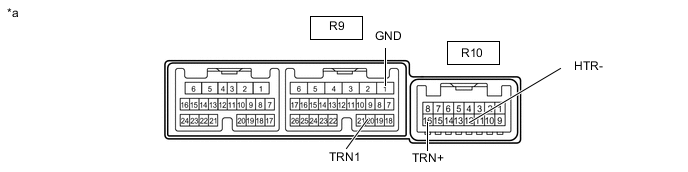
*a Component without harness connected
(Front Multiplex Network Door ECU RH)
- - Standard Resistance Tester Connection Condition Specified Condition R9-20 (TRN1) - R10-16 (TRN+) Always Below 1 Ω R9-1 (GND) - R10-12 (HTR-) Always Below 1 Ω R9-20 (TRN1) - R9-1 (GND) Always 10 kΩ or higher Result Proceed to OK NG
NG
REPLACE FRONT MULTIPLEX NETWORK DOOR ECU RH Click here
OK
-
-
CHECK HARNESS AND CONNECTOR (FRONT MULTIPLEX NETWORK DOOR ECU RH - OUTER MIRROR ACTUATOR ASSEMBLY RH AND BODY GROUND)
-
Disconnect the R10 front multiplex network door ECU RH connector.
-
Disconnect the R6 outer mirror actuator assembly RH connector.
-
Measure the resistance according to the value(s) in the table below.
Standard Resistance (Check for Open) Tester Connection Condition Specified Condition R10-16 (TRN+) - R6-16 (B) Always Below 1 Ω R10-12 (HTR-) - R6-12 (-) Always Below 1 Ω Standard Resistance (Check for Short) Tester Connection Condition Specified Condition R10-16 (TRN+) or R6-16 (B) - Other terminals and body ground Always 10 kΩ or higher R10-12 (HTR-) or R6-12 (-) - Other terminals and body ground Always 10 kΩ or higher Result Proceed to OK NG
NG
REPAIR OR REPLACE HARNESS OR CONNECTOR
OK
-
-
INSPECT SIDE TURN SIGNAL LIGHT ASSEMBLY RH
-
Remove the side turn signal light assembly RH.
-
Inspect the side turn signal light assembly RH.
Result Proceed to OK NG
NG
REPLACE SIDE TURN SIGNAL LIGHT ASSEMBLY RH Click here
OK
-
-
INSPECT OUTER MIRROR ACTUATOR ASSEMBLY RH
-
Remove the outer mirror actuator assembly RH.
-
Inspect the outer mirror actuator assembly RH.
Result Proceed to OK NG
OK
REPLACE COMBINATION METER ASSEMBLY Click here
NG
REPLACE OUTER MIRROR ACTUATOR ASSEMBLY RH Click here
-
-
CHECK HARNESS AND CONNECTOR (COMBINATION METER ASSEMBLY - FRONT TURN SIGNAL LIGHT ASSEMBLY RH)
-
Disconnect the P26 combination meter assembly connector.
-
Disconnect the R9 front multiplex network door ECU RH connector
-
Disconnect the D5 front turn signal light assembly RH connector
-
Measure the resistance according to the value(s) in the table below.
Standard Resistance (Check for Open) Tester Connection Condition Specified Condition P26-7 (LR) - D5-1 (B) Always Below 1 Ω D5-2 (E) - Body ground Always Below 1 Ω Standard Resistance (Check for Short) Tester Connection Condition Specified Condition D5-1 (B) - Body ground Always 10 kΩ or higher Result Proceed to OK NG
NG
REPAIR OR REPLACE HARNESS OR CONNECTOR
OK
-
-
INSPECT FRONT TURN SIGNAL LIGHT ASSEMBLY RH
-
Remove the front turn signal light assembly RH.
-
Inspect the front turn signal light assembly RH.
Result Proceed to OK NG
OK
REPLACE COMBINATION METER ASSEMBLY Click here
NG
REPLACE FRONT TURN SIGNAL LIGHT ASSEMBLY RH Click here
-
-
CHECK HARNESS AND CONNECTOR (REAR COMBINATION LIGHT ASSEMBLY RH - COMBINATION METER ASSEMBLY AND BODY GROUND)
-
Disconnect the X69 rear combination light assembly RH connector.
-
Disconnect the P26 combination meter assembly connector.
-
Measure the resistance according to the value(s) in the table below.
Standard Resistance (Check for Open) Tester Connection Condition Specified Condition X69-4 (TRN) - P26-5 (TRNR) Always Below 1 Ω X69-3 (E) - Body ground Always Below 1 Ω Standard Resistance (Check for Short) Tester Connection Condition Specified Condition X69-4 (TRN) - Body ground Always 10 kΩ or higher Result Proceed to OK NG
NG
REPAIR OR REPLACE HARNESS OR CONNECTOR
OK
-
-
INSPECT REAR COMBINATION LIGHT LENS AND BODY RH
-
Remove the rear combination lens and body RH.
-
Inspect the rear turn signal light assembly RH.
Result Proceed to OK NG
OK
REPLACE COMBINATION METER ASSEMBLY Click here
NG
REPLACE REAR COMBINATION LIGHT LENS AND BODY RH Click here
-
-
CHECK TURN SIGNAL LIGHTS (LH SIDE)
-
Turn the engine switch on (IG).
-
Set the headlight dimmer switch assembly to the left turn switch position.
-
Check the operation of the turn signal lights (LH side).
Result Result Proceed to Side turn signal light assembly (LH side) does not blink. A Front turn signal light assembly (LH side) does not blink. B Rear turn signal light assembly (LH side) does not blink. C
B
CHECK HARNESS AND CONNECTOR (COMBINATION METER ASSEMBLY - FRONT TURN SIGNAL LIGHT ASSEMBLY LH) Click here
C
CHECK HARNESS AND CONNECTOR (REAR COMBINATION LIGHT ASSEMBLY LH - COMBINATION METER ASSEMBLY AND BODY GROUND) Click here
A
-
-
CHECK HARNESS AND CONNECTOR (FRONT MULTIPLEX NETWORK DOOR ECU LH - COMBINATION METER ASSEMBLY AND BODY GROUND)
-
Disconnect the S9 front multiplex network door ECU LH connector.
-
Disconnect the D6 front turn signal light assembly LH connector.
-
Disconnect the P26 combination meter assembly connector.
-
Measure the resistance according to the value(s) in the table below.
Standard Resistance (Check for Open) Tester Connection Condition Specified Condition S9-20 (TRN1) - P26-13 (LL) Always Below 1 Ω S9-1 (GND) - Body ground Always Below 1 Ω Standard Resistance (Check for Short) Tester Connection Condition Specified Condition S9-20 (TRN1) - Body ground Always 10 kΩ or higher Result Proceed to OK NG
NG
REPAIR OR REPLACE HARNESS OR CONNECTOR
OK
-
-
INSPECT FRONT MULTIPLEX NETWORK DOOR ECU LH
-
Remove the front multiplex network door ECU LH.
-
Measure the resistance according to the value(s) in the table below.

*a Component without harness connected
(Front Multiplex Network Door ECU LH)
- - Standard Resistance Tester Connection Condition Specified Condition S9-20 (TRN1) - S10-16 (TRN+) Always Below 1 Ω S9-1 (GND) - S10-12 (HTR-) Always Below 1 Ω S9-20 (TRN1) - S9-1 (GND) Always 10 kΩ or higher Result Proceed to OK NG
NG
REPLACE FRONT MULTIPLEX NETWORK DOOR ECU LH Click here
OK
-
-
CHECK HARNESS AND CONNECTOR (FRONT MULTIPLEX NETWORK DOOR ECU LH - OUTER MIRROR ACTUATOR ASSEMBLY RH AND BODY GROUND)
-
Disconnect the S10 front multiplex network door ECU LH connector.
-
Disconnect the S6 outer mirror actuator assembly LH connector.
-
Measure the resistance according to the value(s) in the table below.
Standard Resistance (Check for Open) Tester Connection Condition Specified Condition S10-16 (TRN+) - S6-16 (B) Always Below 1 Ω S10-12 (HTR-) - S6-12 (-) Always Below 1 Ω Standard Resistance (Check for Short) Tester Connection Condition Specified Condition S10-16 (TRN+) or S6-16 (B) - Other terminals and body ground Always 10 kΩ or higher S10-12 (HTR-) or S6-12 (-) - Other terminals and body ground Always 10 kΩ or higher Result Proceed to OK NG
NG
REPAIR OR REPLACE HARNESS OR CONNECTOR
OK
-
-
INSPECT SIDE TURN SIGNAL LIGHT ASSEMBLY LH
-
Remove the side turn signal light assembly LH.
-
Inspect the side turn signal light assembly LH.
Result Proceed to OK NG
NG
REPLACE SIDE TURN SIGNAL LIGHT ASSEMBLY LH Click here
OK
-
-
INSPECT OUTER MIRROR ACTUATOR ASSEMBLY LH
-
Remove the outer mirror actuator assembly LH.
-
Inspect the outer mirror actuator assembly LH.
Result Proceed to OK NG
OK
REPLACE COMBINATION METER ASSEMBLY Click here
NG
REPLACE OUTER MIRROR ACTUATOR ASSEMBLY LH Click here
-
-
CHECK HARNESS AND CONNECTOR (COMBINATION METER ASSEMBLY - FRONT TURN SIGNAL LIGHT ASSEMBLY LH)
-
Disconnect the P26 combination meter assembly connector.
-
Disconnect the S9 front multiplex network door ECU LH connector
-
Disconnect the D6 front turn signal light assembly LH connector
-
Measure the resistance according to the value(s) in the table below.
Standard Resistance (Check for Open) Tester Connection Condition Specified Condition P26-13 (LL) - D6-1 (B) Always Below 1 Ω D6-2 (E) - Body ground Always Below 1 Ω Standard Resistance (Check for Short) Tester Connection Condition Specified Condition D6-1 (B) - Body ground Always 10 kΩ or higher Result Proceed to OK NG
NG
REPAIR OR REPLACE HARNESS OR CONNECTOR
OK
-
-
INSPECT FRONT TURN SIGNAL LIGHT ASSEMBLY LH
-
Remove the front turn signal light assembly LH.
-
Inspect the front turn signal light assembly LH.
Result Proceed to OK NG
OK
REPLACE COMBINATION METER ASSEMBLY Click here
NG
REPLACE FRONT TURN SIGNAL LIGHT ASSEMBLY LH Click here
-
-
CHECK HARNESS AND CONNECTOR (REAR COMBINATION LIGHT ASSEMBLY LH - COMBINATION METER ASSEMBLY AND BODY GROUND)
-
Disconnect the X70 rear combination light assembly LH connector.
-
Disconnect the P26 combination meter assembly connector.
-
Measure the resistance according to the value(s) in the table below.
Standard Resistance (Check for Open) Tester Connection Condition Specified Condition P26-11 (TRNL) - X70-4 (TRN) Always Below 1 Ω X70-3 (E) - Body ground Always Below 1 Ω Standard Resistance (Check for Short) Tester Connection Condition Specified Condition X70-4 (TRN) - Body ground Always 10 kΩ or higher Result Proceed to OK NG
NG
REPAIR OR REPLACE HARNESS OR CONNECTOR
OK
-
-
INSPECT REAR COMBINATION LIGHT LENS AND BODY LH
-
Remove the rear combination lens and body LH.
-
Inspect the rear turn signal light assembly LH.
Result Proceed to OK NG
OK
REPLACE COMBINATION METER ASSEMBLY Click here
NG
REPLACE REAR COMBINATION LIGHT LENS AND BODY LH Click here
-