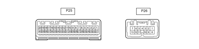
METER / GAUGE SYSTEM TERMINALS OF ECU
-
COMBINATION METER ASSEMBLY
-
Disconnect the combination meter assembly connectors.
-
Measure the voltage on the wire harness side connector according to the value(s) in the table below.
Terminal No. Wiring Color Terminal Description Condition Specified Condition P25-21 (IG+) - Body ground G - Body ground Engine switch signal Engine switch off Below 1 V Engine switch on (IG) 11 to 14 V P25-22 (B) - Body ground V - Body ground Battery Always 11 to 14 V P26-1 (B) - Body ground P - Body ground Battery Always 11 to 14 V P25-39 (ILL-) - Body ground LA-BE - Body ground Illumination signal Headlight dimmer switch off Below 1 V Headlight dimmer switch in tail or head position 11 to 14 V P25-40 (EP) - Body ground W-B - Body ground Ground Always Below 1 Ω If the result is not as specified, there may be a malfunction in the wire harness.
-
Reconnect the combination meter assembly connectors.
-
Measure the voltage and resistance according to the value(s) in the table below.
Terminal No. (Symbol) Wiring Color Terminal Description Condition Specified Condition P25-6 (RLSB) - Body ground LG - Body ground Rear seat belt LH warning light signal Rear seat belt LH fastened within 30 seconds of opening rear door with engine switch on (IG) 11 to 14 V Rear seat belt LH unfastened within 30 seconds of opening rear door with engine switch on (IG) Below 1 V P25-10 (RRSB) - Body ground SB - Body ground Rear seat belt RH warning light signal Rear seat belt RH fastened within 30 seconds of opening rear door with engine switch on (IG) 11 to 14 V Rear seat belt RH unfastened within 30 seconds of opening rear door with engine switch on (IG) Below 1 V P26-6 (INT) - Body ground GR - Body ground Tire pressure warning light signal Engine switch on (IG), tire pressure warning light off Below 1 V Engine switch on (IG), tire pressure warning light on 11 to 14 V P25-20 (SI) - Body ground LG - Body ground Speed signal for other system (Input) Engine switch on (IG), wheel being rotated Pulse generation (See waveform 1) P25-19 (+S) - Body ground L - Body ground Speed signal for other system (Output) Engine switch on (IG), wheel being rotated Pulse generation (See waveform 1) P25-18 (FV) - Body ground B - Body ground Fuel sender gauge (Power source) Always 4.5 to 5.5 V P25-14 (FV) - Body ground R - Body ground Fuel sender gauge (Power source) Always 4.5 to 5.5 V P25-27 (FR) - P25-28 (FE) G - R Fuel level signal Engine switch on (IG) fuel level full Below 1 V Engine switch on (IG) fuel level low (fuel level warning light on) 4.5 to 5.5 V P25-12 (FR) - P25-13 (FE&B) LG - BE Fuel level signal Engine switch on (IG) fuel level full Below 1 V Engine switch on (IG) fuel level low (fuel level warning light on) 4.5 to 5.5 V P25-28 (FE) - Body ground R - Body ground Fuel sender gauge (Ground) Always Below 1 Ω P25-13 (FE&B) - Body ground BE - Body ground Fuel sender gauge (Ground) Always Below 1 Ω P25-16 (WLVL) - Body ground V - Body ground Washer fluid level signal Engine switch on (IG) washer fluid level not low 11 to 14 V Engine switch on (IG) washer fluid level low Below 1 V P25-31 (ES) - Body ground W-B - Body ground Ground Always Below 1 Ω P25-5 (EPB) - Body ground P - Body ground Electric parking brake signal Engine switch on (IG), parking brake switch is off 11 to 14 V Engine switch on (IG), parking brake switch is on Below 1.5 V P25-35 (RLBT) - Body ground W - Body ground Rear seat belt LH warning light signal Front door is opened within approximately 34 seconds after turning the engine switch on (IG) from off and rear seat belt LH unfastened → fastened. In addition, 34 seconds elapse after opening the front door Below 1 V → 11 to 14 V P25-37 (RRBT) - Body ground P - Body ground Rear seat belt RH warning light signal Front door is opened within approximately 34 seconds after turning the engine switch on (IG) from off and rear seat belt RH unfastened → fastened. In addition, 34 seconds elapse after opening the front door Below 1 V → 11 to 14 V P25-30 (CANL) - Body ground W - Body ground CAN communication line - - P25-29 (CANH) - Body ground Y - Body ground CAN communication line - - P26-9 (TX-) - Body ground W - Body ground Local bus communication line - - P26-10 (TX+) - Body ground R- Body ground Local bus communication line - - P25-3 (MSTI) - Body ground B - Body ground Steering pad switch signal Engine switch on (IG), up, down, right and left switches on steering pad switch assembly not pushed 4.3 to 5.2 V Engine switch on (IG), left switch on steering pad switch pushed Below 0.6 V Engine switch on (IG), up switch on steering pad switch pushed 1.0 to 2.2 V Engine switch on (IG), down switch on steering pad switch pushed 2.3 to 3.4 V Engine switch on (IG), right switch on steering pad switch pushed 3.4 to 4.5 V P25-1 (MSSL) - Body ground BR - Body ground Ground Always Below 1 Ω P25-2 (MSM+) - Body ground LG - Body ground Steering pad switch signal Engine switch on (IG), enter, trip and back switches on steering pad switch not pushed 4.3 to 5.2 V Engine switch on (IG), enter switch on steering pad switch pushed Below 0.6 V Engine switch on (IG), trip switch on steering pad switch pushed 1.0 to 2.2 V Engine switch on (IG), back switch on steering pad switch pushed 2.3 to 3.4 V P25-25 (TR) - Body ground BR - Body ground Light control rheostat switch signal Engine switch on (IG), up switch and down switch of trip switch not pushed 4 to 6 V Engine switch on (IG), up switch or down switch of trip switch pushed Below 1 V P25-26 (SW3) - Body ground W - Body ground Ground for trip switch Always Below 1 Ω P25-4 (ODO) - Body ground L - Body ground ODO/TRIP switch signal Engine switch on (IG), ODO/TRIP switch not pushed 4 to 6 V Engine switch on (IG), ODO/TRIP switch pushed Below 1 V P25-9 (S) - Body ground B - Body ground Oil pressure signal Engine started 11 to 14 V Engine not started Below 1 V P25-15 (OILW) - Body ground SB - Body ground Engine oil level signal Engine switch on (IG), engine oil level not low 11 to 14 V Engine switch on (IG), engine oil level low Below 1 V P26-2 (HZSW) - Body ground V - Body ground Hazard warning signal switch signal (Output) Hazard warning signal switch off 11 to 14 V Hazard warning signal switch on Below 1 V P26-12 (HAZM) - Body ground B - Body ground Hazard warning signal switch signal (Output) Engine switch on (IG), hazard warning signal switch not pressed Below 1 V Engine switch on (IG), hazard warning signal switch pressed 11 to 14 V ←→ Below 1 V P26-5 (TRNR) - Body ground SB - Body ground Rear turn signal light RH signal Engine switch on (IG), RH turn indicator light off Below 1 V Engine switch on (IG), RH turn indicator light blinking 11 to 14 V ←→ Below 1 V P26-11 (TRNL) - Body ground Y - Body ground Rear turn signal light LH signal Engine switch on (IG), LH turn indicator light off Below 1 V Engine switch on (IG), LH turn indicator light blinking 11 to 14 V ←→ Below 1 V P26-7 (LR) - Body ground LA-SB - Body ground Rear turn signal light RH signal Engine switch on (IG), RH turn indicator light off Below 1 V Engine switch on (IG), RH turn indicator light blinking 11 to 14 V ←→ Below 1 V P26-13 (LL) - Body ground LA-Y - Body ground Rear turn signal light LH signal Engine switch on (IG), LH turn indicator light off Below 1 V Engine switch on (IG), LH turn indicator light blinking 11 to 14 V ←→ Below 1 V P25-24 (GAGE) - P25-32 (GND) GR - Y Engine oil temperature signal Idling, Engine oil temperature 80 to 105°C (176 to 221°F) 1.24 to 1.94 V If the result is not as specified, the combination meter assembly may be malfunctioning.
-
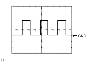
Waveform 1 (Reference):
Item Condition Tool setting 5 V/DIV., 20 ms./DIV. Vehicle condition Engine switch on (IG) wheel being rotated Tech Tips
When the system is functioning normally, one wheel revolution generates 4 pulses. As the vehicle speed increases, the width indicated by (A) in the illustration narrows.
-
-