AUTOMATIC TRANSMISSION SYSTEM, Diagnostic DTC:P27137F
| DTC Code | DTC Name |
|---|---|
| P27137F | Pressure Control Solenoid "D" Actuator Stuck Off |
DESCRIPTION
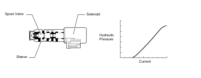
Based on signals from the accelerator position sensor and transmission revolution sensors (NT and SP2), the ECM controls the solenoid (SLT) valve using a predetermined current. As a result, the line pressure is adjusted to a pressure that is appropriate for the throttle angle and engine output. Based on the rotation speed signals from the transmission revolution sensors (NT and SP2), the ECM calculates the heat level of the friction material, and detects clutch slippage, etc.
Tech Tips
| ECM commanded gear | Actual gear during SLT stuck OFF malfunction |
|---|---|
| 1st | 1st or Neutral |
| 2nd | 2nd or Neutral |
| 3rd | 3rd or Neutral |
| 4th | 4th or Neutral |
| 5th | 5th or Neutral |
| 6th | 6th or Neutral |
| 7th | 7th or Neutral |
| 8th | 8th or Neutral |
| 9th | 9th or Neutral |
| 10th | 10th or Neutral |
| DTC No. | Detection Item | DTC Detection Condition | Trouble Area | MIL | Memory | Note |
|---|---|---|---|---|---|---|
| P27137F | Pressure Control Solenoid "D" Actuator Stuck Off | While driving with the shift state in drive (D), the transmission revolution sensor (NT) value exceeds the specified speed for each gear (2-trip detection logic). |
|
Comes on | DTC stored | SAE: P2714 |
MONITOR DESCRIPTION
The ECM calculates the amount of heat absorbed by the friction material based on the difference in revolution speed (clutch slippage) between the turbine and output shaft. The ECM illuminates the MIL and stores this DTC when the amount of heat absorption exceeds the specified value.
When the solenoid (SLT) valve remains OFF, oil pressure goes down and clutch engagement force decreases.
Note
If driving continues under these conditions, the clutches will burn out and the vehicle will no longer be drivable.
CONFIRMATION DRIVING PATTERN
Tech Tips
After repair has been completed, clear the DTC and then check that the vehicle has returned to normal by performing the following All Readiness check procedure.
-
Connect the GTS to the DLC3.
-
Turn the engine switch on (IG) and turn the GTS on.
-
Clear the DTCs (even if no DTCs are stored, perform the clear DTC procedure).
-
Turn the engine switch off and wait for at least 30 seconds.
-
Turn the engine switch on (IG) and turn the GTS on.
-
Perform the D Position Shift Test inspection in Road Test.
-
Enter the following menus: Powertrain / Transmission / Utility / All Readiness.
-
Input the DTC: P27137F.
-
Check the DTC judgment result.
GTS Display Description NORMAL
-
DTC judgment completed
-
System normal
ABNORMAL
-
DTC judgment completed
-
System abnormal
INCOMPLETE
-
DTC judgment not completed
-
Perform driving pattern after confirming DTC enabling conditions
N/A
-
Unable to perform DTC judgment
-
Number of DTCs which do not fulfill DTC preconditions has reached ECU memory limit
Tech Tips
-
If the judgment result shows NORMAL, the system is normal.
-
If the judgment result shows ABNORMAL, the system has a malfunction.
-
If the judgment result shows INCOMPLETE or N/A, perform the Confirmation Driving Pattern and check the DTC judgment result again.
-
CAUTION / NOTICE / HINT
Note
Perform registration and/or initialization when parts related to the automatic transmission are replaced.
PROCEDURE
-
CHECK DTC OUTPUT (IN ADDITION TO DTC P27137F)
-
Connect the GTS to the DLC3.
-
Turn the engine switch on (IG).
-
Turn the GTS on.
-
Enter the following menus: Powertrain / Transmission / Trouble Codes.
Powertrain > Transmission > Trouble Codes -
Read the DTCs using the GTS.
Result Result Proceed to DTC P27137F and DTC P07407E, P07457F, P076A71, P07707E, P07707F, P07757F, P07957F, P08BA7F, P08CC7E, P08CC7F, P08D57E, P08D57F, P27567F, P28077F and/or P28167F are output A Only DTC P27137F is output B DTCs other than P07407E, P07457F, P076A71, P07707E, P07707F, P07757F, P07957F, P08BA7F, P08CC7E, P08CC7F, P08D57E, P08D57F, P27137F, P27567F, P28077F and P28167F are also output C Tech Tips
If any DTCs other than P07407E, P07457F, P076A71, P07707E, P07707F, P07757F, P07957F, P08BA7F, P08CC7E, P08CC7F, P08D57E, P08D57F, P27137F, P27567F, P28077F and P28167F are output, perform troubleshooting for those DTCs first.
B 
GO TO STEP 6 Click here
C 
GO TO DTC CHART Click here
A 
-
-
CLEAR DTC AND PERFORM STALL SPEED TEST
-
Clear the DTCs.
Tech Tips
Write down the currently output DTCs before clearing them.
Powertrain > Transmission > Clear DTCs -
Perform the stall speed test.
Result Test Condition Proceed to Stall speed test can be performed A Stall speed test cannot be performed B
B
GO TO STEP 6 Click here
A
-
-
INSPECT SOLENOID (SL1), (SL2), (SL3), (SL4), (SL5), (SL6) AND (SLU) VALVE
-
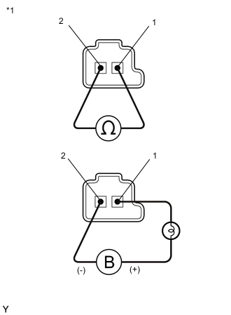
*1 Solenoid (SL1), (SL2), (SL3), (SL4), (SL5), (SL6) and (SLU) Valves Remove the solenoid (SL1), (SL2), (SL3), (SL4), (SL5), (SL6) and (SLU) valves.
-
Measure the resistance according to the value(s) in the table below.
Standard Resistance Tester Connection Condition Specified Condition Solenoid (SL1) valve connector terminal 1 - terminal 2 20°C (68°F) 5.0 to 5.6 Ω Solenoid (SL2) valve connector terminal 1 - terminal 2 20°C (68°F) 5.0 to 5.6 Ω Solenoid (SL3) valve connector terminal 1 - terminal 2 20°C (68°F) 5.0 to 5.6 Ω Solenoid (SL4) valve connector terminal 1 - terminal 2 20°C (68°F) 5.0 to 5.6 Ω Solenoid (SL5) valve connector terminal 1 - terminal 2 20°C (68°F) 5.0 to 5.6 Ω Solenoid (SL6) valve connector terminal 1 - terminal 2 20°C (68°F) 5.0 to 5.6 Ω Solenoid (SLU) valve connector terminal 1 - terminal 2 20°C (68°F) 5.0 to 5.6 Ω -
Connect a positive (+) lead from the battery with a 21 W bulb to terminal 1 and a negative (-) lead to terminal 2 of the solenoid valve connector. Check that the valve moves and makes an operating sound.
OK Valve moves and makes an operating sound. Result Proceed to OK NG
NG
REPLACE SOLENOID (SL1), (SL2), (SL3), (SL4), (SL5), (SL6) OR (SLU) VALVE Click here
OK
-
-
INSPECT SOLENOID (SC1), (SC2) AND (SC3) VALVE
-
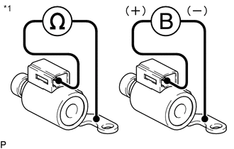
*1 Solenoid (SC1), (SC2) and (SC3) Valves Remove the solenoid (SC1), (SC2) and (SC3) valves.
-
Measure the resistance according to the value(s) in the table below.
Standard Resistance Tester Connection Condition Specified Condition Terminal of solenoid (SC1) valve connector - Solenoid (SC1) valve body 20°C (68°F) 11 to 15 Ω Terminal of solenoid (SC2) valve connector - Solenoid (SC2) valve body 20°C (68°F) 11 to 15 Ω Terminal of solenoid (SC3) valve connector - Solenoid (SC3) valve body 20°C (68°F) 11 to 15 Ω -
Connect a positive (+) lead from the battery to the terminal of the solenoid valve connector, and a negative (-) lead to the solenoid body. Check that the valve moves and makes an operating sound.
OK Valve moves and makes an operating sound. Result Proceed to OK NG
NG
REPLACE SOLENOID (SC1), (SC2) OR (SC3) VALVE Click here
OK
-
-
INSPECT SOLENOID (SL) AND (SR) VALVE
-
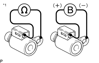
*1 Solenoid (SL) and (SR) Valves Remove the solenoid (SL) and (SR) valves.
-
Measure the resistance according to the value(s) in the table below.
Standard Resistance Tester Connection Condition Specified Condition Terminal of solenoid (SL) valve connector - Solenoid (SL) valve body 20°C (68°F) 11 to 15 Ω Terminal of solenoid (SR) valve connector - Solenoid (SR) valve body 20°C (68°F) 11 to 15 Ω -
Connect a positive (+) lead from the battery to the terminal of the solenoid valve connector, and a negative (-) lead to the solenoid body. Check that the valve moves and makes an operating sound.
OK Valve moves and makes an operating sound. Result Proceed to OK NG
NG
REPLACE SOLENOID (SL) OR (SR) VALVE Click here
OK
-
-
INSPECT SOLENOID (SLT) VALVE
-
*1 Solenoid (SLT) Valve Remove the solenoid (SLT) valve.
-
Measure the resistance according to the value(s) in the table below.
Standard Resistance Tester Connection Condition Specified Condition 1 - 2 20°C (68°F) 5.0 to 5.6 Ω -
Connect a positive (+) lead from the battery with a 21 W bulb to terminal 1 and a negative (-) lead to terminal 2 of the solenoid valve connector. Check that the valve moves and makes an operating sound.
OK Valve moves and makes an operating sound. Result Proceed to OK NG
NG
REPLACE SOLENOID (SLT) VALVE Click here
OK
-
-
INSPECT TRANSMISSION VALVE BODY ASSEMBLY
-
Check the transmission valve body assembly.
OK There is no foreign matter on each valve and they operate smoothly. Result Proceed to OK NG
NG
REPAIR OR REPLACE TRANSMISSION VALVE BODY ASSEMBLY Click here
OK
-
-
INSPECT TORQUE CONVERTER ASSEMBLY
-
Check the torque converter assembly.
OK The torque converter operates normally. Result Proceed to OK NG
NG
REPLACE TORQUE CONVERTER ASSEMBLY Click here
OK
-
-
REPAIR OR REPLACE AUTOMATIC TRANSMISSION ASSEMBLY
-
Repair or replace the automatic transmission assembly.
Result Proceed to NEXT
NEXT
PERFORM A/T CODE REGISTRATION Click here
-