AUTOMATIC TRANSMISSION SYSTEM, Diagnostic DTC:P076A11
| DTC Code | DTC Name |
|---|---|
| P076A11 | Shift Solenoid "H" Control Circuit Short to Ground |
DESCRIPTION
Based on the ON-OFF combinations of the solenoid (SL1, SL2, SL3, SL4, SL5, SL6, SC1, SC2, SC3 and SR) valves, the ECM performs gear shifts from 1st gear to 10th gear.
If a circuit related to a solenoid valve is open or shorted, the ECM uses the fail-safe function to turn other solenoid valves ON or OFF. If an open or short has occurred, the ECM cuts power to the malfunctioning solenoid valve.
Tech Tips
The following table shows normal operation of the solenoid (SC1) valve when the shift state is in drive (D).
| Gear | Solenoid (SC1) Valve |
|---|---|
| 1st | ON |
| 2nd | ON |
| 3rd | ON |
| 4th | OFF |
| 5th | OFF |
| 6th | OFF |
| 7th | OFF |
| 8th | OFF |
| 9th | OFF |
| 10th | OFF |
| DTC No. | Detection Item | DTC Detection Condition | Trouble Area | MIL | Memory | Note |
|---|---|---|---|---|---|---|
| P076A11 | Shift Solenoid "H" Control Circuit Short to Ground | The solenoid (SC1) valve terminal low voltage occurs 2 times per trip, when the solenoid (SC1) valve is operated (1-trip detection logic). |
|
Comes on | DTC stored | SAE: P099E |
MONITOR DESCRIPTION
This DTC indicates a short in the solenoid (SC1) valve circuit. When there is an open or short in any solenoid valve circuit, the ECM detects the problem, illuminates the MIL and stores a DTC.
When the solenoid (SC1) valve is on, if its resistance is 8 Ω or less, the ECM determines there is a short in the solenoid (SC1) valve circuit.
CONFIRMATION DRIVING PATTERN
Tech Tips
After repair has been completed, clear the DTC and then check that the vehicle has returned to normal by performing the following All Readiness check procedure.
-
Connect the GTS to the DLC3.
-
Turn the engine switch on (IG) and turn the GTS on.
-
Clear the DTCs (even if no DTCs are stored, perform the clear DTC procedure).
-
Turn the engine switch off and wait for at least 30 seconds.
-
Turn the engine switch on (IG) and turn the GTS on.
-
Perform the D Position Shift Test inspection in Road Test.
-
Enter the following menus: Powertrain / Transmission / Utility / All Readiness.
-
Input the DTC: P076A11.
-
Check the DTC judgment result.
GTS Display Description NORMAL
-
DTC judgment completed
-
System normal
ABNORMAL
-
DTC judgment completed
-
System abnormal
INCOMPLETE
-
DTC judgment not completed
-
Perform driving pattern after confirming DTC enabling conditions
N/A
-
Unable to perform DTC judgment
-
Number of DTCs which do not fulfill DTC preconditions has reached ECU memory limit
Tech Tips
-
If the judgment result shows NORMAL, the system is normal.
-
If the judgment result shows ABNORMAL, the system has a malfunction.
-
If the judgment result shows INCOMPLETE or N/A, perform the Confirmation Driving Pattern and check the DTC judgment result again.
-
WIRING DIAGRAM
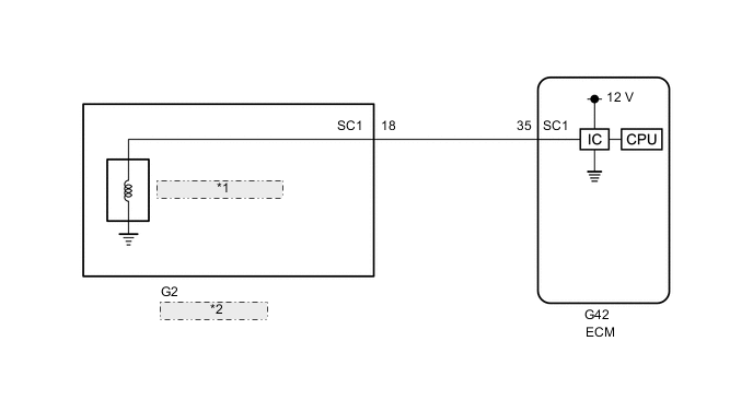
| *1 | Solenoid (SC1) Valve |
| *2 | Transmission Wire |
CAUTION / NOTICE / HINT
Note
Perform registration and/or initialization when parts related to the automatic transmission are replaced.
PROCEDURE
-
CHECK HARNESS AND CONNECTOR (TRANSMISSION WIRE (SOLENOID (SC1) VALVE) - ECM)
-
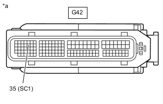
*a Front view of wire harness connector
(to ECM)
Disconnect the ECM connector.
-
Measure the resistance according to the value(s) in the table below.
Standard Resistance Tester Connection Condition Specified Condition G42-35 (SC1) - Body ground 20°C (68°F) 11 to 15 Ω Result Proceed to OK NG
NG 
CHECK HARNESS AND CONNECTOR (TRANSMISSION WIRE - ECM) Click here
OK 
-
-
REPLACE ECM
-
Replace the ECM.
Result Proceed to NEXT
NEXT 
PERFORM A/T CODE REGISTRATION Click here
-
-
CHECK HARNESS AND CONNECTOR (TRANSMISSION WIRE - ECM)
-
Disconnect the G2 transmission wire connector.
-
Disconnect the G42 ECM connector.
-
Measure the resistance according to the value(s) in the table below.
Standard Resistance Tester Connection Condition Specified Condition G2-18 (SC1) or G42-35 (SC1) - Body ground and other terminals Always 10 kΩ or higher Result Proceed to OK NG
NG
REPAIR OR REPLACE HARNESS OR CONNECTOR
OK
-
-
INSPECT SOLENOID (SC1) VALVE
-
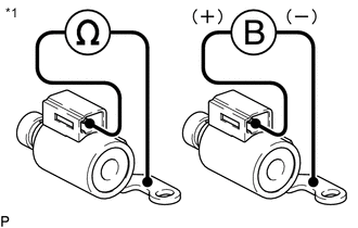
*1 Solenoid (SC1) Valve Remove the solenoid (SC1) valve.
-
Measure the resistance according to the value(s) in the table below.
Standard Resistance Tester Connection Condition Specified Condition Terminal of solenoid (SC1) valve connector - Solenoid (SC1) valve body 20°C (68°F) 11 to 15 Ω -
Connect a positive (+) lead from the battery to the terminal of the solenoid valve connector, and a negative (-) lead to the solenoid body. Check that the valve moves and makes an operating sound.
OK Valve moves and makes an operating sound. Result Proceed to OK NG
OK
REPAIR OR REPLACE TRANSMISSION WIRE Click here
NG
REPLACE SOLENOID (SC1) VALVE Click here
-