OIL PUMP REMOVAL

PROCEDURE
-
INSTALL ENGINE STAND
-
REMOVE ENGINE WIRE
-
DISCONNECT NO. 5 ENGINE WIRE
-
REMOVE THROTTLE BODY WITH MOTOR ASSEMBLY
-
REMOVE INJECTOR DRIVER
-
REMOVE INJECTOR DRIVER BRACKET
-
REMOVE WATER BY-PASS PIPE SUB-ASSEMBLY
-
REMOVE PURGE VSV
-
DISCONNECT VACUUM HOSE SUB-ASSEMBLY
-
REMOVE FUEL VAPOR FEED HOSE
-
REMOVE NO. 2 PCV HOSE
-
REMOVE NO. 3 PCV HOSE
-
DISCONNECT PCV HOSE
-
REMOVE FUEL TUBE SUB-ASSEMBLY
-
REMOVE NO. 2 FUEL DELIVERY PIPE SUB-ASSEMBLY
-
REMOVE FUEL DELIVERY PIPE SUB-ASSEMBLY
-
REMOVE NO. 1 DELIVERY PIPE SPACER
-
REMOVE INJECTOR VIBRATION INSULATOR
-
DISCONNECT NO. 1 FUEL PIPE SUB-ASSEMBLY
-
REMOVE INTAKE AIR SURGE TANK ASSEMBLY
-
REMOVE NO. 1 ENGINE COVER SUB-ASSEMBLY
-
REMOVE NO. 1 FUEL PIPE SUB-ASSEMBLY
-
REMOVE NO. 3 FUEL PIPE SUB-ASSEMBLY
-
REMOVE NO. 2 FUEL PIPE SUB-ASSEMBLY
-
REMOVE FUEL PUMP WITH SEAL SUB-ASSEMBLY (for Bank 1)
-
REMOVE FUEL PUMP WITH SEAL SUB-ASSEMBLY (for Bank 2)
-
REMOVE NO. 2 IDLER PULLEY SUB-ASSEMBLY
-
REMOVE OIL PUMP DRIVE SHAFT PULLEY
-
REMOVE WATER PUMP PULLEY
-
REMOVE WATER INLET HOUSING
-
REMOVE NO. 2 WATER BY-PASS PIPE SUB-ASSEMBLY
-
REMOVE IGNITION COIL ASSEMBLY
-
REMOVE FRONT WATER BY-PASS JOINT
-
REMOVE OIL FILTER BRACKET SUB-ASSEMBLY
-
REMOVE CRANKSHAFT PULLEY ASSEMBLY
-
REMOVE CRANKSHAFT TIMING GEAR KEY
-
REMOVE CYLINDER HEAD COVER SUB-ASSEMBLY LH
-
REMOVE CYLINDER HEAD COVER SUB-ASSEMBLY
-
REMOVE SPARK PLUG TUBE GASKET
-
REMOVE V-RIBBED BELT TENSIONER ASSEMBLY
-
REMOVE CAM TIMING CONTROL MOTOR WITH EDU ASSEMBLY LH
-
REMOVE CAM TIMING CONTROL MOTOR WITH EDU ASSEMBLY RH
-
REMOVE TIMING CHAIN COVER ASSEMBLY
-
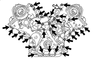

Bolt 
Nut Remove the 30 bolts and nut shown in the illustration.
-
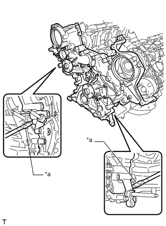
*a Protective Tape Remove the timing chain cover assembly by prying between the timing chain cover assembly and cylinder head sub-assembly and cylinder head LH or cylinder block sub-assembly with a screwdriver.
Note
Be careful not to damage the contact surfaces of the cylinder head sub-assembly, cylinder head LH or cylinder block sub-assembly and timing chain cover assembly.
Tech Tips
Tape the screwdriver tip before use.
-
Remove the oil pump gasket from the cylinder block sub-assembly.
-
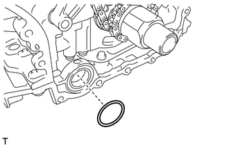
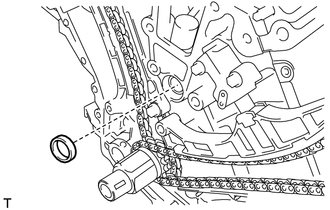
Remove the O-ring from the cylinder block sub-assembly.
-
-
REMOVE TIMING GEAR CASE OR TIMING CHAIN CASE OIL SEAL
-
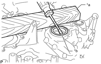
*a Wooden Block *b Protective Tape Using a screwdriver and wooden block, pay out the timing gear case or timing chain case oil seal.
Note
Do not damage the surface of the timing gear case or timing chain case oil seal press fit hole.
Tech Tips
Tape the screwdriver tip before use.
-
-
REMOVE WATER INLET PIPE
-
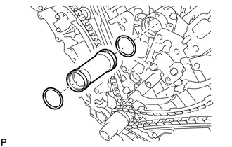
Remove the water inlet pipe.
-
Remove the 2 O-rings from the inlet water pipe.
-
-
REMOVE NO. 1 OIL PIPE
-
REMOVE NO. 2 OIL PIPE
-
REMOVE NO. 3 OIL PIPE
-
REMOVE SCAVENGING PUMP ASSEMBLY