EXHAUST PIPE INSTALLATION
PROCEDURE
-
INSTALL EXHAUST PIPE GAS CONTROL ACTUATOR SUB-ASSEMBLY
-
New article:
-
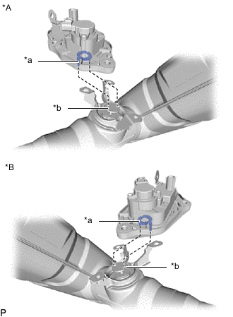
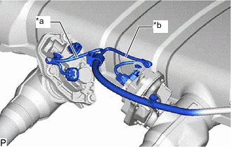
*A for RH Side *B for LH Side *a Joint *b Valve Plate Align the joint of the exhaust pipe gas control actuator sub-assembly with the valve plate of the exhaust tailpipe assembly as shown in the illustration.
-
Install the 2 exhaust pipe gas control actuator sub-assemblies with the 6 bolts and 4 nuts.
- Torque:
- 21 N*m { 214 kgf*cm, 15 ft.*lbf }
Note
Install the same parts to their original positions.
-
-
Reuse:
-
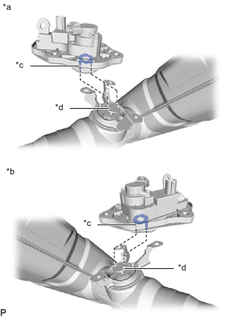
*A for RH Side *B for LH Side *a Joint *b Valve Plate Align the joint of the exhaust pipe gas control actuator sub-assembly with the valve plate of the exhaust tailpipe assembly as shown in the illustration.
-
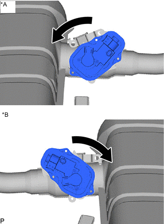
*A for RH Side *B for LH Side Turn the exhaust pipe gas control actuator sub-assembly as shown in the illustration.
-
Install the 2 exhaust pipe gas control actuator sub-assemblies with the 6 bolts and 4 nuts.
- Torque:
- 21 N*m { 214 kgf*cm, 15 ft.*lbf }
Note
Install the same parts to their original positions.
-
-
-
INSTALL EXHAUST TAILPIPE ASSEMBLY
-
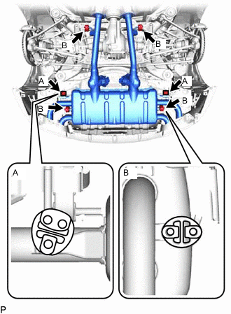
Install the 6 exhaust pipe supports to the exhaust tailpipe assembly as shown in the illustration.
-
*a Black *b White Attach the 2 clamps and connect the 4 connectors as shown in the illustration.
-
-
INSTALL FRONT EXHAUST PIPE ASSEMBLY
-
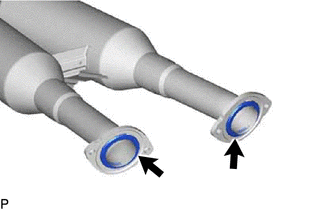
Install 2 new gaskets to the front exhaust pipe assembly of the rear side.
-
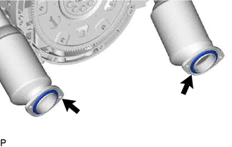
Install 2 new gaskets to the exhaust manifold sub-assembly RH and exhaust manifold sub-assembly LH.
-
Install the front exhaust pipe assembly to the exhaust tailpipe assembly with 4 new nuts and 4 new bolts.
- Torque:
- 39 N*m { 398 kgf*cm, 29 ft.*lbf }
Note
Do not reuse the bolt, nut and gasket.
-
Install the front exhaust pipe assembly to the exhaust manifold sub-assembly RH and exhaust manifold sub-assembly LH with 4 new nuts and 4 new bolts.
- Torque:
- 39 N*m { 398 kgf*cm, 29 ft.*lbf }
Note
Do not reuse the bolt, nut and gasket.
-
-
INSTALL REAR NO. 4 BUMPER SIDE SUPPORT RH
-
Install the rear No. 4 bumper side support RH with the 2 screws, 2 clips and grommet.
-
-
INSTALL REAR NO. 4 BUMPER SIDE SUPPORT LH
-
Install the rear No. 4 bumper side support LH with the 2 screws, 2 clips and grommet.
-
-
INSTALL NO. 1 DIFFERENTIAL SUPPORT PROTECTOR
-
Install the No. 1 differential support protector with the 3 nuts.
- Torque:
- 8.0 N*m { 82 kgf*cm, 6 ft.*lbf }
-
-
INSTALL NO. 2 DIFFERENTIAL SUPPORT PROTECTOR
-
Install the No. 2 differential support protector with the 3 nuts.
- Torque:
- 8.0 N*m { 82 kgf*cm, 6 ft.*lbf }
-
-
INSTALL FRONT CENTER FLOOR BRACE SUB-ASSEMBLY
-
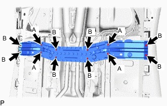
Install the front center floor brace sub-assembly with the 12 bolts.
- Torque:
- 20 N*m { 204 kgf*cm, 15 ft.*lbf }
Bolt Length Item Length Bolt A 21 mm (0.827 in.) Bolt B 44 mm (1.73 in.)
-
-
INSTALL HEATED OXYGEN SENSOR (for Bank 2)
-
INSTALL HEATED OXYGEN SENSOR (for Bank 1)
-
CONNECT HEATED OXYGEN SENSOR
-
INSTALL FRONT SEAT ASSEMBLY
-
INSTALL FRONT FLOOR COVER RH
-
Install the front floor cover RH with the 3 clips and grommet.
-
-
INSTALL FRONT FLOOR COVER LH
-
Install the front floor cover LH with the 3 clips and grommet.
-
-
INSTALL FRONT FENDER SEAL RH
-
Install the front fender seal RH with the 6 clips, 4 grommets, nut and bolt.
- Torque:
- 8.0 N*m { 82 kgf*cm, 6 ft.*lbf }
-
-
INSTALL FRONT FENDER SEAL LH
-
Install the front fender seal LH with the 6 clips, 4 grommets, nut and bolt.
- Torque:
- 8.0 N*m { 82 kgf*cm, 6 ft.*lbf }
-
-
INSTALL REAR FLOOR SIDE MEMBER COVER RH
-
Install the rear floor side member cover RH with the 2 clips, 3 bolts, nut, and screw.
- Torque:
- 8.0 N*m { 82 kgf*cm, 6 ft.*lbf }
-
-
INSTALL REAR FLOOR SIDE MEMBER COVER LH
-
Install the rear floor side member cover LH with the 2 clips, 3 bolts, nut, and screw.
- Torque:
- 8.0 N*m { 82 kgf*cm, 6 ft.*lbf }
-
-
INSPECT FOR EXHAUST GAS LEAK
If gas is leaking, tighten the areas necessary to stop the leak. Replace damaged parts as necessary.
If an exhaust gas leak has been repaired, perform an inspection following the repair.
-
w/ Canister Pump Module:
-
w/o Canister Pump Module:
-