EXHAUST MANIFOLD INSTALLATION

PROCEDURE
-
INSTALL EXHAUST MANIFOLD TO HEAD GASKET
-
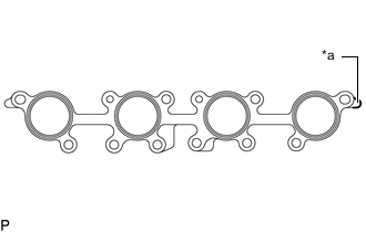
*a Paint Mark Install a new exhaust manifold to head gasket to the cylinder head sub-assembly.
Note
Attach it with a painted aspect as the exhaust manifold sub-assembly RH side.
-
-
INSTALL EXHAUST MANIFOLD SUB-ASSEMBLY RH
-
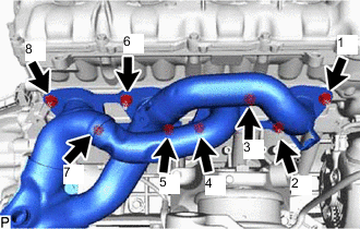
Temporarily install the exhaust manifold sub-assembly RH to the cylinder head sub-assembly with the 8 nuts.
-
Tighten the 8 nuts in the order shown in the illustration.
- Torque:
- 21 N*m { 214 kgf*cm, 15 ft.*lbf }
-
-
INSTALL NO. 1 EXHAUST MANIFOLD HEAT INSULATOR
-
Install the No. 1 exhaust manifold heat insulator to the exhaust manifold sub-assembly RH with the 3 bolts.
- Torque:
- 10 N*m { 102 kgf*cm, 7 ft.*lbf }
-
-
INSTALL ENGINE OIL LEVEL DIPSTICK GUIDE
-
Apply a light coat of engine oil to a new O-ring.
-
Install the O-ring to the engine oil level dipstick guide.
-
Install the engine oil level dipstick guide with the bolt.
- Torque:
- 10 N*m { 102 kgf*cm, 7 ft.*lbf }
-
Install the engine oil level dipstick to the engine oil level dipstick guide.
-
-
INSTALL EXHAUST MANIFOLD TO HEAD GASKET LH
-
*a Paint Mark Install a new exhaust manifold to head gasket LH to the cylinder head sub-assembly.
Note
Attach it with a painted aspect as the exhaust manifold sub-assembly LH side.
-
-
INSTALL EXHAUST MANIFOLD SUB-ASSEMBLY LH
-
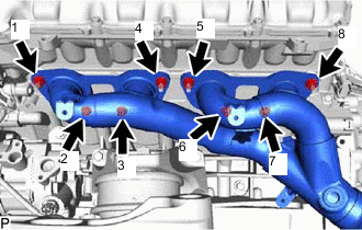
Temporarily install the exhaust manifold sub-assembly LH to the cylinder head sub-assembly with the 8 nuts.
-
Tighten the 8 nuts in the order shown in the illustration.
- Torque:
- 21 N*m { 214 kgf*cm, 15 ft.*lbf }
-
-
INSTALL NO. 2 EXHAUST MANIFOLD HEAT INSULATOR
-
Install the No. 2 exhaust manifold heat insulator to the exhaust manifold sub-assembly LH with the 3 bolts.
- Torque:
- 10 N*m { 102 kgf*cm, 7 ft.*lbf }
-
-
INSTALL ENGINE MOUNTING DAMPER
-
Install the engine mounting damper to the front No. 1 engine mount bracket with the bolt.
- Torque:
- 10 N*m { 102 kgf*cm, 7 ft.*lbf }
-
-
INSTALL AIR FUEL RATIO SENSOR (for Bank 2)
Tech Tips
Perform "Inspection After Repair" after replacing an air fuel ratio sensor.
-
w/ Canister Pump Module:
-
w/o Canister Pump Module:
-
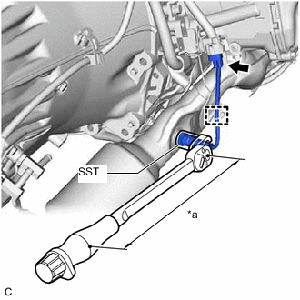
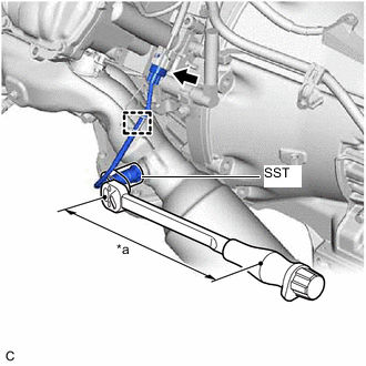
*a Torque Wrench Fulcrum Length Using SST, install the air fuel ratio sensor to the exhaust manifold RH.
- SST
- 09224-00012
- Torque:
- Specified tightening torque
- 44 N*m { 449 kgf*cm, 32 ft.*lbf }
Note
If the air fuel ratio sensor has been struck or dropped, replace it.
Tech Tips
-
Calculate the torque wrench reading when changing the fulcrum length of the torque wrench.
-
When using SST (fulcrum length of 30 mm (1.18 in.)) + torque wrench (fulcrum length of 260 mm (10.2 in.)):
37.7 N*m (384 kgf*cm, 28 ft.*lbf)
-
Attach the wire harness clamp.
-
Connect the air fuel ratio sensor connector.
-
-
INSTALL AIR FUEL RATIO SENSOR (for Bank 1)
Tech Tips
Perform "Inspection After Repair" after replacing an air fuel ratio sensor.
-
w/ Canister Pump Module:
-
w/o Canister Pump Module:
-
*a Torque Wrench Fulcrum Length Using SST, install the air fuel ratio sensor to the exhaust manifold LH.
- SST
- 09224-00012
- Torque:
- Specified tightening torque
- 44 N*m { 449 kgf*cm, 32 ft.*lbf }
Note
If the air fuel ratio sensor has been struck or dropped, replace it.
Tech Tips
-
Calculate the torque wrench reading when changing the fulcrum length of the torque wrench.
-
When using SST (fulcrum length of 30 mm (1.18 in.)) + torque wrench (fulcrum length of 260 mm (10.2 in.)):
37.7 N*m (384 kgf*cm, 28 ft.*lbf)
-
Attach the wire harness clamp.
-
Connect the air fuel ratio sensor connector.
-
-
INSTALL ENGINE WITH TRANSMISSION ASSEMBLY
-
INSPECT FOR EXHAUST GAS LEAK