INTAKE SYSTEM ON-VEHICLE INSPECTION
CAUTION / NOTICE / HINT
The necessary procedures (adjustment, calibration, initialization, or registration) that must be performed after parts are removed, installed, or replaced when repairing air leaks in the intake system are shown below.
| Replacement Part or Procedure | Necessary Procedure | Effect/Inoperative when not Performed | Link |
|---|---|---|---|
| Air leak from intake system is repaired | Inspection After Repair |
|
|
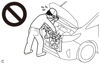
CAUTION:
-
When working near the engine room while the engine has started or the power source mode is engine switch on (IG), do not touch the fan and generator V belt or rotating components such as the fan, etc.
-
Touching the fan and generator V belt or rotating components such as the fan, etc. could result in your hand or clothing getting caught and pulled in.
PROCEDURE
-
INSPECT INTAKE SYSTEM
Tech Tips
Perform "Inspection After Repair" after repairing vacuum leaks in the intake system.
-
w/ Canister Pump Module:
-
w/o Canister Pump Module:
-
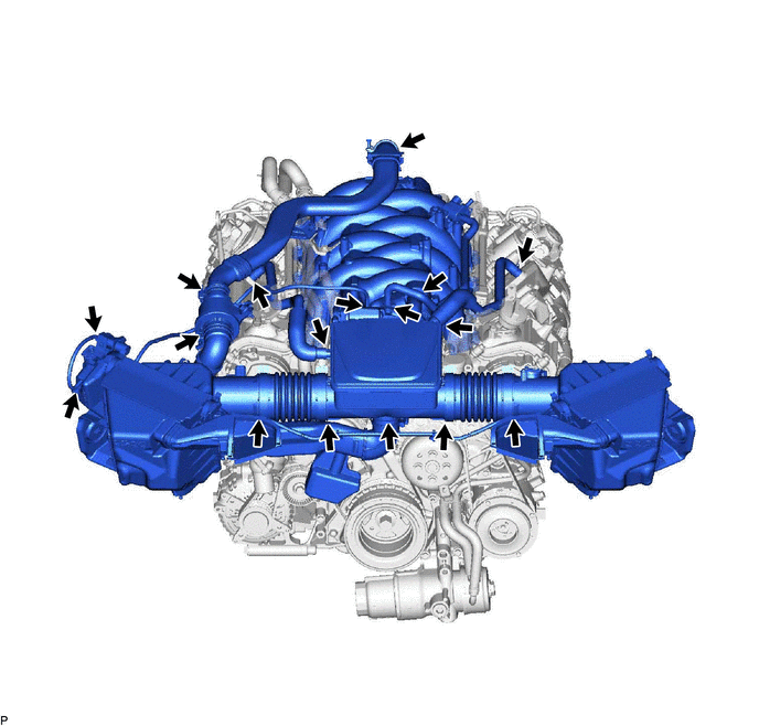
Check that there are no vacuum leaks at the points shown in the illustration.
-
-
INSPECT INTAKE AIR CONTROL VALVE ACTUATOR
-
for Air Cleaner with Element Assembly RH Side:
-
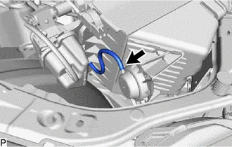
Disconnect the vacuum hose.
-
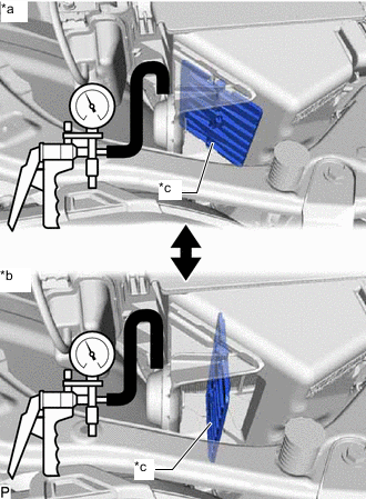
*a Vacuum released *b Vacuum applied *c Intake Air Control Valve Confirm that the intake air control valve opens smoothly under vacuum and closes smoothly when the vacuum is released.
If the intake air control valve does not close or open smoothly, replace the air cleaner assembly.
-
Connect the vacuum hose.
-
-
for Air Cleaner with Element Assembly LH Side:
-
Disconnect the vacuum hose.
-
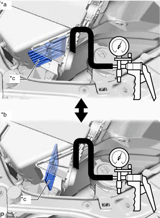
*a Vacuum released *b Vacuum applied *c Intake Air Control Valve Confirm that the intake air control valve opens smoothly under vacuum and closes smoothly when the vacuum is released.
If the intake air control valve does not close or open smoothly, replace the air cleaner assembly.
-
Connect the vacuum hose.
-
-
-
INSPECT VACUUM SWITCHING VALVE ASSEMBLY (for AICV)
-
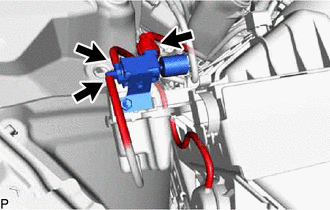
Disconnect the vacuum switching valve assembly (for AICV) connector.
-
Disconnect the 2 vacuum hoses from the vacuum switching valve assembly (for AICV).
-
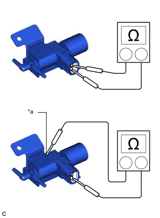
*a Body Ground Measure the resistance according to the value(s) in the table below.
Standard Resistance Tester Connection Condition Specified Condition 1 - 2 20°C (68°F) 37 to 44 Ω 1 - Body ground Always 10 kΩ or higher 2 - Body ground Always 10 kΩ or higher If the result is not as specified, replace the air cleaner assembly.
-
Check the operation of the vacuum switching valve assembly (for AICV).
-
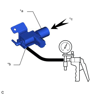
*a Filter *b Port (E) *c Air When vacuum is applied to the port (E), check that air is sucked into the filter.
If air is not sucked into the filter, replace the air cleaner assembly.
-
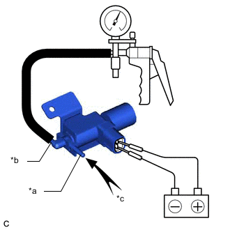
*a Port (E) *b Port (F) *c Air Apply battery voltage across the terminals. When vacuum is applied to the port (F), check that air is sucked into the port (E).
If air is not sucked into the port (F), replace the air cleaner assembly.
-
-