CANISTER(w/o Canister Pump Module) ON-VEHICLE INSPECTION
PROCEDURE
-
INSPECT CHARCOAL CANISTER ASSEMBLY
-
Visually check the charcoal canister assembly for cracks or damage.
If cracks or damage is found, replace the charcoal canister assembly.
-
Check charcoal canister assembly operation under positive pressure.
-
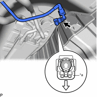
*a Retainer 
Pull Disconnect the fuel suction tube sub-assembly from the charcoal canister assembly.
-
Pinch the retainer to detach the lock claw and pull it.
Note
-
Remove any dirt or foreign matter on the tube connector before performing this work.
-
Do not allow any scratches or foreign matter to get on the parts when disconnecting them as the tube connector has an O-ring that seals the pipe (charcoal canister assembly).
-
Perform this work by hand. Do not use any tools.
-
Do not forcibly bend, twist or turn the fuel suction tube sub-assembly.
-
Protect the disconnected parts by covering them with plastic bags after disconnecting the fuel suction tube sub-assembly.
-
If the tube connector and pipe (charcoal canister assembly) are stuck, push and pull to release them.
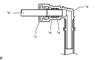
*a Tube Connector *b Pipe (Charcoal Canister Assembly) *c Retainer *d O-Ring Tech Tips
Do not remove the retainer.
-
-
Pull off the fuel suction tube sub-assembly from the pipe (charcoal canister assembly).
-
-
Close the fuel suction tube sub-assembly using a hose plug or a similar part.
-
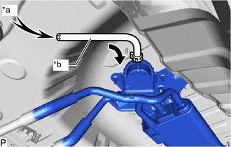
*a Air *b Test Hose Connect a test hose to the charcoal canister assembly.
-
Blow 8 kPa (0.1 kgf/cm2, 1.2 psi) of air into the test hose and check that air passes through the charcoal canister assembly.
OK Air flow freely If the result is not as specified, inspect the fuel outlet valve assembly and charcoal canister assembly.
-
Disconnect the test hose from the charcoal canister assembly.
-

*a Retainer Push Push the fuel suction tube sub-assembly to the charcoal canister assembly and push in the retainer to attach the lock claws.
Note
-
Check that there are no scratches or foreign matter around the connecting parts of the tube connector and pipe (charcoal canister assembly) before performing this work.
-
After connecting the fuel suction tube sub-assembly, check that the fuel suction tube sub-assembly is securely connected by pulling on the tube connector.
-
-
-
Check charcoal canister assembly operation under vacuum.
-
*a Retainer Pull Disconnect the fuel suction tube sub-assembly from the charcoal canister assembly.
-
Pinch the retainer to detach the lock claw and pull it.
Note
-
Remove any dirt or foreign matter on the tube connector before performing this work.
-
Do not allow any scratches or foreign matter to get on the parts when disconnecting them as the tube connector has an O-ring that seals the pipe (charcoal canister assembly).
-
Perform this work by hand. Do not use any tools.
-
Do not forcibly bend, twist or turn the fuel suction tube sub-assembly.
-
Protect the disconnected parts by covering them with plastic bags after disconnecting the fuel suction tube sub-assembly.
-
If the tube connector and pipe (charcoal canister assembly) are stuck, push and pull to release them.
*a Tube Connector *b Pipe (Charcoal Canister Assembly) *c Retainer *d O-Ring Tech Tips
Do not remove the retainer.
-
-
Pull off the fuel suction tube sub-assembly from the pipe (charcoal canister assembly).
-
-
Close the fuel suction tube sub-assembly using a hose plug or a similar part.
-
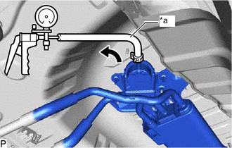
*a Test Hose Connect a test hose to the charcoal canister assembly.
-
Connect a vacuum pump to the test hose.
-
Using the vacuum pump, apply vacuum and check that the vacuum pump indicator does not move from its initial position.
OK The indicator needle of the vacuum pump does not rise from its initial position. Tech Tips
The vacuum pump indicator may move when applying vacuum. If the vacuum pump indicator quickly returns to its initial position, the canister (charcoal canister assembly) is operating normally.
If the result is not as specified, inspect the fuel outlet valve assembly and charcoal canister assembly.
-
Disconnect the vacuum pump from the test hose.
-
Disconnect the test hose from the charcoal canister assembly.
-
*a Retainer Push Push the fuel suction tube sub-assembly to the charcoal canister assembly and push in the retainer to attach the lock claws.
Note
-
Check that there are no scratches or foreign matter around the connecting parts of the tube connector and pipe (charcoal canister assembly) before performing this work.
-
After connecting the fuel suction tube sub-assembly, check that the fuel suction tube sub-assembly is securely connected by pulling on the tube connector.
-
-
-
Check for clogs in the air filter (when not using the GTS).
-
*a Retainer Pull Disconnect the fuel suction tube sub-assembly from the charcoal canister assembly.
-
Pinch the retainer to detach the lock claw and pull it.
Note
-
Remove any dirt or foreign matter on the tube connector before performing this work.
-
Do not allow any scratches or foreign matter to get on the parts when disconnecting them as the tube connector has an O-ring that seals the pipe (charcoal canister assembly).
-
Perform this work by hand. Do not use any tools.
-
Do not forcibly bend, twist or turn the fuel suction tube sub-assembly.
-
Protect the disconnected parts by covering them with plastic bags after disconnecting the fuel suction tube sub-assembly.
-
If the tube connector and pipe (charcoal canister assembly) are stuck, push and pull to release them.
*a Tube Connector *b Pipe (Charcoal Canister Assembly) *c Retainer *d O-Ring Tech Tips
Do not remove the retainer.
-
-
Pull off the fuel suction tube sub-assembly from the pipe (charcoal canister assembly).
-
-
Close the fuel suction tube sub-assembly using a hose plug or a similar part.
-
*a Test Hose Connect a test hose to the charcoal canister assembly.
-
Connect a vacuum pump to the test hose.
-
Start the engine.
-
Warm up the engine.
-
Idle the engine for 15 minutes and check that the vacuum pump indicator does not move from its initial position.
OK The indicator needle of the vacuum pump does not rise from its initial position. Tech Tips
The vacuum pump indicator may move when the purge valve (purge VSV) opens to vacuum. If the vacuum pump indicator quickly returns to its initial position, the canister (charcoal canister assembly) is operating normally.
-
Disconnect the vacuum pump from the test hose.
-
Disconnect the test hose from the charcoal canister assembly.
-
*a Retainer Push Push the fuel suction tube sub-assembly to the charcoal canister assembly and push in the retainer to attach the lock claws.
Note
-
Check that there are no scratches or foreign matter around the connecting parts of the tube connector and pipe (charcoal canister assembly) before performing this work.
-
After connecting the fuel suction tube sub-assembly, check that the fuel suction tube sub-assembly is securely connected by pulling on the tube connector.
-
-
-
Check for clogs in the air filter (when using the GTS).
Tech Tips
When performing an Active Test of the purge valve (purge VSV) using the GTS, it is not necessary to warm up and idle the engine for 15 minutes.
-
*a Retainer Pull Disconnect the fuel suction tube sub-assembly from the charcoal canister assembly.
-
Pinch the retainer to detach the lock claw and pull it.
Note
-
Remove any dirt or foreign matter on the tube connector before performing this work.
-
Do not allow any scratches or foreign matter to get on the parts when disconnecting them as the tube connector has an O-ring that seals the pipe (charcoal canister assembly).
-
Perform this work by hand. Do not use any tools.
-
Do not forcibly bend, twist or turn the fuel suction tube sub-assembly.
-
Protect the disconnected parts by covering them with plastic bags after disconnecting the fuel suction tube sub-assembly.
-
If the tube connector and pipe (charcoal canister assembly) are stuck, push and pull to release them.
*a Tube Connector *b Pipe (Charcoal Canister Assembly) *c Retainer *d O-Ring Tech Tips
Do not remove the retainer.
-
-
Pull off the fuel suction tube sub-assembly from the pipe (charcoal canister assembly).
-
-
Close the fuel suction tube sub-assembly using a hose plug or a similar part.
-
*a Test Hose Connect a test hose to the charcoal canister assembly.
-
Connect a vacuum pump to the test hose.
-
Connect the GTS to the DLC3.
-
Start the engine.
-
Enter the following menus: Powertrain / Engine / Active Test / Purge VSV
Powertrain > Engine > Active TestTester Display Activate the EVAP Purge VSV OK The indicator needle of the vacuum pump does not rise from its initial position. Tech Tips
-
When the engine idling, perform the Active Test
-
The vacuum pump indicator may move when the purge valve (purge VSV) opens to vacuum. If the vacuum pump indicator quickly returns to its initial position, the canister (charcoal canister assembly) is operating normally.
-
-
Disconnect the vacuum pump from the test hose.
-
Disconnect the test hose from the charcoal canister assembly.
-
*a Retainer Push Push the fuel suction tube sub-assembly to the charcoal canister assembly and push in the retainer to attach the lock claws.
Note
-
Check that there are no scratches or foreign matter around the connecting parts of the tube connector and pipe (charcoal canister assembly) before performing this work.
-
After connecting the fuel suction tube sub-assembly, check that the fuel suction tube sub-assembly is securely connected by pulling on the tube connector.
-
-
-