FUEL PUMP(for High Pressure) INSTALLATION
PROCEDURE
-
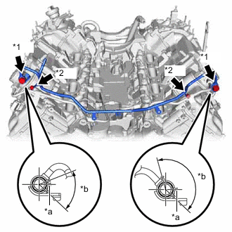
SET FUEL PUMP WITH SEAL SUB-ASSEMBLY (for Bank 1)
-
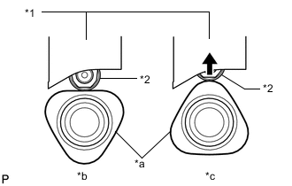
*1 Fuel Pump Lifter Guide *2 Fuel Pump Lifter Assembly *a Cam Lobe *b Correct *c Incorrect Turn the crankshaft pulley until the flat of the cam lobe faces the fuel pump with seal sub-assembly installation hole of the cylinder head cover sub-assembly LH.
Tech Tips
This prevent the cam nose from pushing up the pump lifter when installing the fuel pump with seal sub-assembly.
-
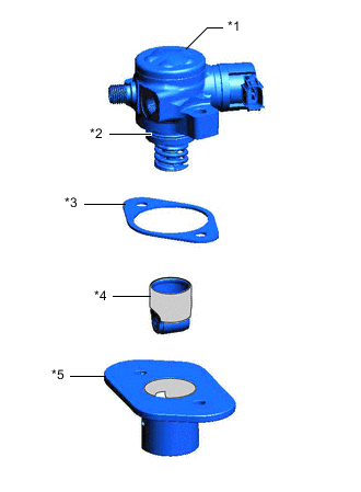
*1 Fuel Pump with Seal Sub-assembly *2 O-ring *3 Fuel Pump Insulator *4 Fuel Pump Lifter Assembly *5 Fuel Pump Lifter Guide 
Engine Oil Application Area Apply engine oil to a new O-ring and install it to the fuel pump sub-assembly.
-
Apply engine oil to the inside of the fuel pump lifter guide and the outside of the fuel pump lifter assembly.
-
Install the fuel pump lifter assembly to the fuel pump lifter guide.
-
Install the fuel pump insulator to the fuel pump lifter guide.
-
Install the fuel pump with seal sub-assembly to the fuel pump lifter guide.
-
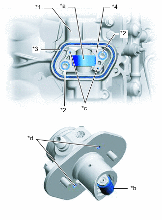
*1 Cylinder Head Cover Sub-assembly LH *2 O-ring *3 Fuel Pump Spacer Gasket *4 No. 4 Camshaft Bearing Cap *a Pump Drive Cam (Engine Oil Application Area) *b Pump Lifter (Engine Oil Application Area) *c Knock Pin *d Pin Hole Apply 30 cc (1.8 cu in.) of engine oil to the pump drive cam.
-
Apply engine oil to the fuel pump lifter assembly.
-
Apply engine oil to 2 new O-rings and install them to the No. 4 camshaft bearing cap.
-
Install a new fuel pump spacer gasket to the cylinder head cover sub-assembly LH.
-
Set the fuel pump with seal sub-assembly on the cylinder head cover sub-assembly LH.
-
Temporarily install the fuel pump with seal sub-assembly with the 2 bolts, leaving some allowance for left and right movement.
-
-
SET FUEL PUMP WITH SEAL SUB-ASSEMBLY (for Bank 2)
Tech Tips
Use the same procedure as for the bank 1 side.
-
TEMPORARILY INSTALL NO. 2 FUEL PIPE SUB-ASSEMBLY
-
Connect the No. 2 fuel pipe sub-assembly to the fuel delivery pipe RH and tighten the union nut by hand.
-
Connect the No. 2 fuel pipe sub-assembly to the fuel pump with seal sub-assembly and tighten the union nut by hand.
Note
Do not damage the seals of the union nuts of the No. 2 fuel pipe sub-assembly when installing.
-
Temporarily install the bolt.
-
-
TEMPORARILY INSTALL NO. 3 FUEL PIPE SUB-ASSEMBLY
-
Connect the No. 3 fuel pipe sub-assembly to the fuel delivery pipe LH and tighten the union nut by hand.
-
Connect the No. 3 fuel pipe sub-assembly to the fuel pump with seal sub-assembly and tighten the union nut by hand.
Note
Do not damage the seals of the union nuts of the No. 3 fuel pipe sub-assembly when installing.
-
Temporarily install the bolt.
-
-
INSTALL FUEL PUMP WITH SEAL SUB-ASSEMBLY (for Bank 1)
-
Tighten the 2 bolts.
- Torque:
- 30 N*m { 306 kgf*cm, 22 ft.*lbf }
-
-
INSTALL FUEL PUMP WITH SEAL SUB-ASSEMBLY (for Bank 2)
Tech Tips
Use the same procedure as for the bank 1 side.
-
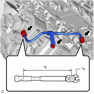
INSTALL NO. 2 FUEL PIPE SUB-ASSEMBLY
-
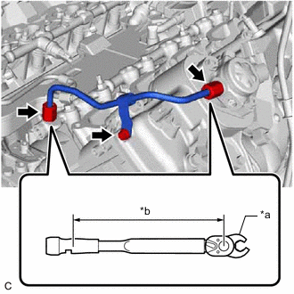
*a 17 mm Union Nut Wrench *b Torque Wrench Fulcrum Length Using a 17 mm union nut wrench, tighten the union nuts on the fuel pump with seal sub-assembly side of the No. 2 fuel pipe sub-assembly.
- Torque:
- Specified tightening torque
- 35 N*m { 357 kgf*cm, 26 ft.*lbf }
Tech Tips
-
Calculate the torque wrench reading when changing the fulcrum length of the torque wrench.
-
When using a 17 mm union nut wrench (fulcrum length of 30 mm (1.18 in.)) + torque wrench (fulcrum length of 180 mm (7.09 in.)): 30 N*m (306 kgf*cm, 22 ft.*lbf)
-
Using a 17 mm union nut wrench, tighten the union nuts on the fuel delivery pipe RH side of the No. 2 fuel pipe sub-assembly.
- Torque:
- Specified tightening torque
- 35 N*m { 357 kgf*cm, 26 ft.*lbf }
Tech Tips
-
Calculate the torque wrench reading when changing the fulcrum length of the torque wrench.
-
When using a 17 mm union nut wrench (fulcrum length of 30 mm (1.18 in.)) + torque wrench (fulcrum length of 180 mm (7.09 in.)): 30 N*m (306 kgf*cm, 22 ft.*lbf)
-
Tighten the bolt.
- Torque:
- 10 N*m { 102 kgf*cm, 7 ft.*lbf }
-
-
INSTALL NO. 3 FUEL PIPE SUB-ASSEMBLY
-
*a 17 mm Union Nut Wrench *b Torque Wrench Fulcrum Length Using a 17 mm union nut wrench, tighten the union nuts on the fuel pump with seal sub-assembly side of the No. 3 fuel pipe sub-assembly.
- Torque:
- Specified tightening torque
- 35 N*m { 357 kgf*cm, 26 ft.*lbf }
Tech Tips
-
Calculate the torque wrench reading when changing the fulcrum length of the torque wrench.
-
When using a 17 mm union nut wrench (fulcrum length of 30 mm (1.18 in.)) + torque wrench (fulcrum length of 180 mm (7.09 in.)): 30 N*m (306 kgf*cm, 22 ft.*lbf)
-
Using a 17 mm union nut wrench, tighten the union nuts on the fuel delivery pipe LH side of the No. 3 fuel pipe sub-assembly.
- Torque:
- Specified tightening torque
- 35 N*m { 357 kgf*cm, 26 ft.*lbf }
Tech Tips
-
Calculate the torque wrench reading when changing the fulcrum length of the torque wrench.
-
When using a 17 mm union nut wrench (fulcrum length of 30 mm (1.18 in.)) + torque wrench (fulcrum length of 180 mm (7.09 in.)): 30 N*m (306 kgf*cm, 22 ft.*lbf)
-
Tighten the bolt.
- Torque:
- 10 N*m { 102 kgf*cm, 7 ft.*lbf }
-
-
INSTALL NO. 1 FUEL PIPE SUB-ASSEMBLY
-
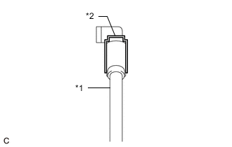
*1 No. 1 Fuel Pipe Sub-assembly *2 Gasket Install 2 new gaskets to the No. 1 fuel pipe sub-assembly.
-
*1 Union Bolt *2 Bolt *a Protrusion *b Protrusion Area Install the No. 1 fuel pipe sub-assembly with the 4 bolts.
- Torque:
- for Union Bolt
- 35 N*m { 357 kgf*cm, 26 ft.*lbf }
- for Bolt
- 10 N*m { 102 kgf*cm, 7 ft.*lbf }
Tech Tips
Install the gaskets within the area shown in the illustration.
-
-
INSTALL NO. 3 COVER SUB-ASSEMBLY
-
Install the No. 3 cover sub-assembly to the No. 1 fuel pipe sub-assembly with the 2 clips.
-
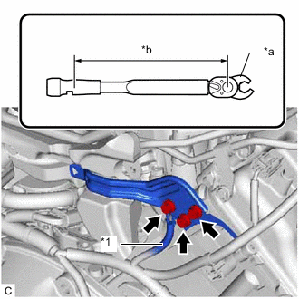
*1 No. 2 Engine Wire *a 10 mm Union Nut Wrench *b Torque Wrench Fulcrum Length Using a 10 mm union nut wrench, install the wire harness bracket to the cylinder head sub-assembly with the 2 bolts.
- Torque:
- Specified tightening torque
- 10 N*m { 102 kgf*cm, 7 ft.*lbf }
Tech Tips
-
Calculate the torque wrench reading when changing the fulcrum length of the torque wrench.
-
When using a 10 mm union nut wrench (fulcrum length of 22 mm (0.866 in.)) + torque wrench (fulcrum length of 155 mm (6.1 in.)): 9.0 N*m (92 kgf*cm, 80 in.*lbf)
-
Using a 10 mm union nut wrench, connect the No. 2 engine wire with the bolt.
- Torque:
- Specified tightening torque
- 10 N*m { 102 kgf*cm, 7 ft.*lbf }
Tech Tips
-
Calculate the torque wrench reading when changing the fulcrum length of the torque wrench.
-
When using a 10 mm union nut wrench (fulcrum length of 22 mm (0.866 in.)) + torque wrench (fulcrum length of 155 mm (6.1 in.)): 9.0 N*m (92 kgf*cm, 80 in.*lbf)
-
Engage the clamp to connect the engine wire to the wire harness bracket.
-
-
INSTALL NO. 1 ENGINE COVER SUB-ASSEMBLY
-
Install the No. 1 engine cover sub-assembly.
-
-
CONNECT INLET HEATER WATER HOSE
-
CONNECT OUTLET HEATER WATER HOSE
-
INSTALL INTAKE AIR SURGE TANK ASSEMBLY
-
CONNECT FUEL TUBE SUB-ASSEMBLY
-
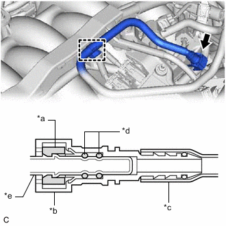
*a Retainer *b Fuel Tube Connector *c Nylon Tube *d O-ring *e Fuel Pipe Connect the fuel tube sub-assembly to the No. 1 fuel pipe sub-assembly.
Note
Check if there is any damage or foreign matter on the connecting parts of the fuel pipe.
-
Attach the clamp to connect the fuel tube sub-assembly to the engine wire.
-
-
CONNECT CABLE TO NEGATIVE BATTERY TERMINAL
Note
When disconnecting the cable, some systems need to be initialized after the cable is reconnected.
-
INSPECT FOR FUEL LEAK
-
PERFORM INITIALIZATION
-
Perform "Inspection After Repair" after replacing the fuel pump with seal sub-assembly.
-
w/ Canister Pump Module:
-
w/o Canister Pump Module:
-
-