FUEL PUMP(for High Pressure) REMOVAL
CAUTION / NOTICE / HINT
The necessary procedures (adjustment, calibration, initialization, or registration) that must be performed after parts are removed, installed, or replaced during the fuel pump with seal sub-assembly removal/installation are shown below.
| Replacement Part or Procedure | Necessary Procedure | Effect/Inoperative when not Performed | Link |
|---|---|---|---|
| Disconnect cable from negative battery terminal | Memorize steering angle neutral point | LKA /LDA system | |
| Pre-collision system | |||
| Parking assist monitor system | |||
| Steering sensor zero point calibration | Variable gear ratio steering system | ||
| Replacement of fuel pump with seal sub-assembly (for high pressure side) | Inspection After Repair |
|
|
CAUTION:
-
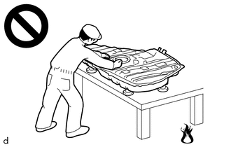
Never perform work on fuel system components near any possible ignition sources.
-
Vaporized fuel could ignite, resulting in a serious accident.
-
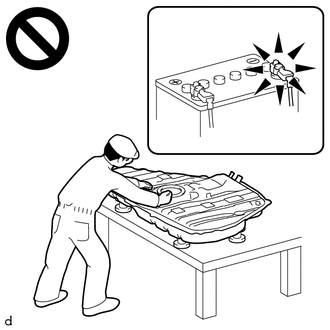
Do not perform work on fuel system components without first disconnecting the cable from the negative (-) battery terminal.
-
Sparks could cause vaporized fuel to ignite, resulting in a serious accident.
PROCEDURE
-
DISCHARGE FUEL SYSTEM PRESSURE
-
PRECAUTION
Note
After turning the engine switch off, waiting time may be required before disconnecting the cable from the negative (-) battery terminal. Therefore, make sure to read the disconnecting the cable from the negative (-) battery terminal notices before proceeding with work.
-
DISCONNECT CABLE FROM NEGATIVE BATTERY TERMINAL
Note
When disconnecting the cable, some systems need to be initialized after the cable is reconnected.
-
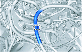
DISCONNECT FUEL TUBE SUB-ASSEMBLY
Note
Remove any dirt or foreign matter on the fuel tube connector and fuel pipe before performing this work.
-
Disconnect the fuel tube sub-assembly from the No. 1 fuel pipe sub-assembly.
-
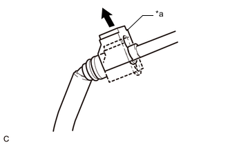
*a Fuel Tube Connector Cover 
Pull off Pull off the fuel tube connector cover.
-
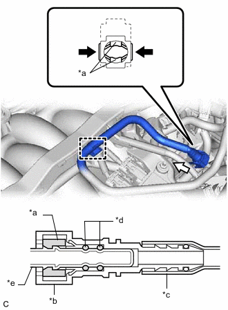
*a Retainer *b Fuel Tube Connector *c Nylon Tube *d O-ring *e Fuel Pipe Pinch 
Pull Disengage the clamp to disconnect the fuel tube sub-assembly from the engine wire.
-
Pinch the retainer of the fuel tube connector, and then pull the fuel tube connector off of the fuel pipe.
Note
Be sure to disconnect the fuel tube connector by hand.
-
If the fuel tube connector and fuel pipe are stuck, push and pull the fuel tube connector to release it. Pull the fuel tube connector off of the fuel pipe carefully.
Note
-
Be sure to disconnect the fuel tube connector by hand.
-
Do not allow any scratches or foreign matter to get on the parts when disconnecting them as the fuel tube connector has O-rings that seal the fuel pipe.
-
Do not forcibly bend, twist or turn the nylon tube.
-
-
Check if there is any foreign matter on the sealing surfaces of the disconnected fuel lines. Clean them if necessary.
-
Cover the disconnected fuel pipe and fuel tube connector with plastic bags to prevent damage and contamination.
-
-
-
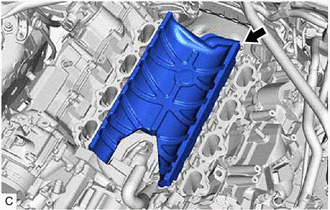
REMOVE INTAKE AIR SURGE TANK ASSEMBLY
-
DISCONNECT OUTLET HEATER WATER HOSE
-
DISCONNECT INLET HEATER WATER HOSE
-
REMOVE NO. 1 ENGINE COVER SUB-ASSEMBLY
-
Remove the No. 1 engine cover sub-assembly.
-
-
REMOVE NO. 3 COVER SUB-ASSEMBLY
-
Disengage the clamp to disconnect the engine wire from the wire harness bracket.
-
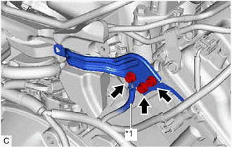
*1 No. 2 Engine Wire Remove the bolt to disconnect the No. 2 engine wire.
-
Remove the 2 bolts and wire harness bracket from the cylinder head sub-assembly.
-
Remove the 2 clips and No. 3 cover sub-assembly from the No. 1 fuel pipe sub-assembly.
-
-
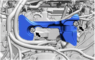
REMOVE NO. 1 FUEL PIPE SUB-ASSEMBLY
-
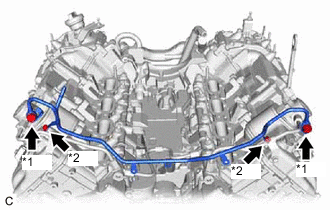
*1 Union Bolt *2 Bolt Remove the 2 bolts, 2 union bolts and No. 1 fuel pipe sub-assembly.
-
Remove the 2 gaskets from the No. 1 fuel pipe sub-assembly.
-
-
REMOVE NO. 3 FUEL PIPE SUB-ASSEMBLY
-
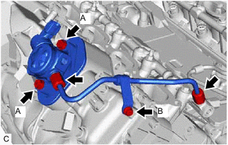
Using a 17 mm union nut wrench, loosen the 2 union nuts of the No. 3 fuel pipe sub-assembly.
-
Loosen the 2 bolts (A).
-
Remove the bolt (B).
-
Remove the No. 3 fuel pipe sub-assembly from the fuel delivery pipe LH and fuel pump with seal sub-assembly.
-
-
REMOVE NO. 2 FUEL PIPE SUB-ASSEMBLY
-
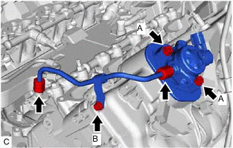
Using a 17 mm union nut wrench, loosen the 2 union nuts of the No. 2 fuel pipe sub-assembly.
-
Loosen the 2 bolts (A).
-
Remove the bolt (B).
-
Remove the No. 2 fuel pipe sub-assembly from the fuel delivery pipe RH and fuel pump with seal sub-assembly.
-
-
REMOVE FUEL PUMP WITH SEAL SUB-ASSEMBLY (for Bank 1)
-
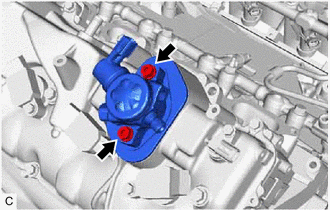
Remove the 2 bolts and fuel pump with seal sub-assembly from the cylinder head cover sub-assembly LH.
-
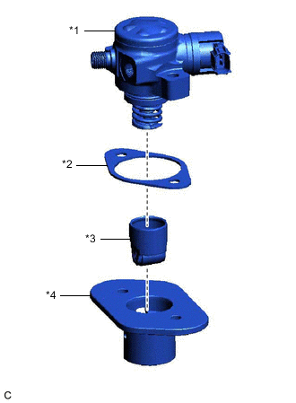
*1 Fuel Pump with Seal Sub-assembly *2 Fuel Pump Insulator *3 Fuel Pump Lifter Assembly *4 Fuel Pump Lifter Guide Remove the fuel pump lifter guide, fuel pump lifter assembly and fuel pump insulator from the fuel pump with seal sub-assembly.
-
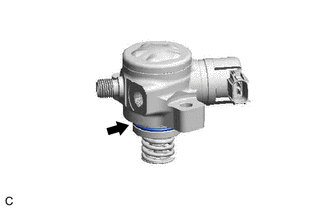
Remove the O-ring from the fuel pump sub-assembly.
-
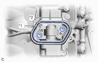
*1 Fuel Pump Spacer Gasket *2 O-ring Remove the fuel pump spacer gasket from the cylinder head cover sub-assembly LH.
-
Remove the 2 O-rings from the No. 4 camshaft bearing cap.
-
-
REMOVE FUEL PUMP WITH SEAL SUB-ASSEMBLY (for Bank 2)
Tech Tips
Use the same procedure as for the bank 1 side.