FUEL INJECTOR(for Port Injection) INSTALLATION

PROCEDURE
-
INSTALL PORT FUEL INJECTOR ASSEMBLY
Tech Tips
Perform "Inspection After Repair" after replacing a port fuel injector assembly.
-
w/ Canister Pump Module:
-
w/o Canister Pump Module:
-
Apply a light coat of spindle oil or gasoline to a new O-ring, and install one to each port fuel injector assembly.
Note
Check that there is no damage or foreign matter on the groove of the port fuel injector assembly when installing each O-ring to the port fuel injector assembly.
-
Connect the 8 port fuel injector assembly connector.
-
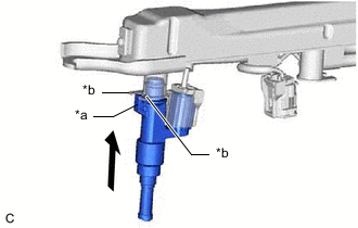
*a Claw *b Stopper Install the 8 port fuel injector assemblies to the fuel delivery pipe sub-assembly and No. 2 fuel delivery pipe sub-assembly.
Note
-
Make sure that the port fuel injector assembly is located within the stopper as shown in the illustration.
-
Check that there is no damage or foreign matter on the port fuel injector assembly installation holes.
-
When installing the O-ring, make sure they do not become pinched or cut.
-
-
Engage the 3 clamps to connect the No. 6 engine wire to the fuel delivery pipe sub-assembly.
-
Engage the 3 clamps to connect the No. 7 engine wire to the No. 2 fuel delivery pipe sub-assembly.
-
-
INSTALL INJECTOR VIBRATION INSULATOR
-
Install 8 new injector vibration insulators to the intake air surge tank assembly.
-
-
INSTALL NO. 1 DELIVERY PIPE SPACER
-
Install the 4 No. 1 delivery pipe spacers to the intake air surge tank assembly.
-
-
INSTALL FUEL DELIVERY PIPE SUB-ASSEMBLY (for Bank 2)
-
Place the fuel delivery pipe sub-assembly with the port fuel injector assemblies onto the intake air surge tank assembly.
Note
Be careful not to drop the port fuel injector assemblies when installing the fuel delivery pipe sub-assembly.
-
Install the fuel delivery pipe sub-assembly with the port fuel injector assemblies with the 2 bolts.
- Torque:
- 21 N*m { 214 kgf*cm, 15 ft.*lbf }
-
-
INSTALL NO. 2 FUEL DELIVERY PIPE SUB-ASSEMBLY (for Bank 1)
-
Place the No. 2 fuel delivery pipe sub-assembly with the port fuel injector assemblies onto the intake air surge tank assembly.
Note
Be careful not to drop the port fuel injector assemblies when installing the No. 2 fuel delivery pipe sub-assembly.
-
Install the No. 2 fuel delivery pipe sub-assembly with the port fuel injector assemblies with the 2 bolts.
- Torque:
- 21 N*m { 214 kgf*cm, 15 ft.*lbf }
-
-
INSTALL FUEL TUBE SUB-ASSEMBLY
-
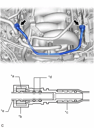
*a Retainer *b Fuel Tube Connector *c Nylon Tube *d O-ring *e Fuel Pipe Install the fuel tube sub-assembly to the fuel delivery pipe sub-assembly and No. 2 fuel delivery pipe sub-assembly.
Note
Check if there is any damage or foreign matter on the connecting parts of the fuel pipe.
-
-
INSTALL PURGE VALVE (PURGE VSV)
-
INSTALL WATER BY-PASS PIPE SUB-ASSEMBLY
-
INSTALL INJECTOR DRIVER BRACKET
-
INSTALL INJECTOR DRIVER
-
ENGAGE ENGINE WIRE
-
INSTALL NO. 2 ENGINE UNDER COVER ASSEMBLY
-
INSTALL AIR CLEANER HOSE CLAMP
-
INSTALL NO. 2 INTAKE AIR CONNECTOR PIPE
-
INSTALL INTAKE AIR SOUND CREATOR
-
INSTALL INTAKE AIR CONNECTOR PIPE
-
INSTALL AIR CLEANER WITH ELEMENT CLEANER ASSEMBLY LH
-
INSTALL AIR CLEANER WITH ELEMENT ASSEMBLY RH
-
INSTALL RADIATOR SUPPORT TO CROSS MEMBER BRACE SUB-ASSEMBLY RH
-
INSTALL RADIATOR SUPPORT TO CROSS MEMBER BRACE SUB-ASSEMBLY LH
-
INSTALL THROTTLE BODY WITH MOTOR ASSEMBLY
-
CONNECT NO. 2 FUEL TUBE SUB-ASSEMBLY
-
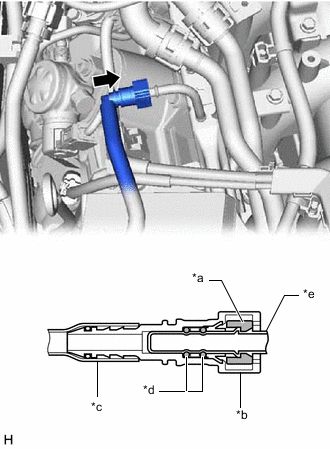
*a Retainer *b Fuel Tube Connector *c Nylon Tube *d O-ring *e Fuel Pipe 
Push Connect the No. 2 fuel tube sub-assembly to the fuel delivery pipe sub-assembly.
Note
Check if there is any damage or foreign matter on the connecting parts of the fuel lines.
-
Install the No. 2 fuel tube sub-assembly to the fuel pipe (for Vehicle side).
-
Install the fuel pipe clamp to the fuel tube connector.
-
Attach the 2 claws to install a new No. 2 fuel pipe clamp.
-
-
CONNECT CABLE TO NEGATIVE BATTERY TERMINAL
Note
When disconnecting the cable, some systems need to be initialized after the cable is reconnected.
-
INSPECT FOR FUEL LEAK
-
PERFORM INITIALIZATION
-
Perform "Inspection After Repair" after replacing a port fuel injector assembly.
-
w/ Canister Pump Module:
-
w/o Canister Pump Module:
-
-