CYLINDER BLOCK DISASSEMBLY
CAUTION / NOTICE / HINT
The necessary procedures (adjustment, calibration, initialization, or registration) that must be performed after parts are removed, installed, or replaced during the cylinder block sub-assembly disassembly/reassembly are shown below.
| Replacement Part or Procedure | Necessary Procedure | Effect/Inoperative when not Performed | Link |
|---|---|---|---|
| Disconnect cable from negative battery terminal | Memorize steering angle neutral point | LKA/LDA system | |
| Pre-collision system | |||
| Parking assist monitor system | |||
| Steering sensor zero point calibration | Variable gear ratio steering system | ||
|
Inspection After Repair |
|
w/ Canister Pump Module: Click here w/o Canister Pump Module: Click here |
| Engine assembly | Inspection After Repair | ||
|
|
||
| Automatic transmission assembly |
|
|
for Initialization: Click here for Registration: Click here |
| Automatic transmission fluid | ATF thermal degradation estimate reset | The value of the Data List item "ATF Thermal Degradation Estimate" is not estimated correctly. | |
| Parts between the steering wheel and tires have been removed/installed, replaced or adjusted | Perform Actuator Angle Neutral Point Calibration and Initialization |
|
*1: New automatic transmission's compensation code.
*2: w/ Canister Pump Module
PROCEDURE
-
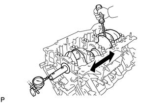
INSPECT CONNECTING ROD THRUST CLEARANCE
-
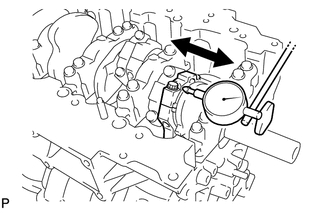
Using a dial indicator, measure the connecting rod thrust clearance while moving the connecting rod sub-assembly back and forth.
Standard Thrust Clearance 0.15 to 0.55 mm (0.00591 to 0.0217 in.) Maximum Thrust Clearance 0.70 mm (0.0276 in.) If the connecting rod thrust clearance is more than the maximum, replace the connecting rod sub-assembly. If necessary, replace the crankshaft.
-
-
INSPECT CONNECTING ROD OIL CLEARANCE
-
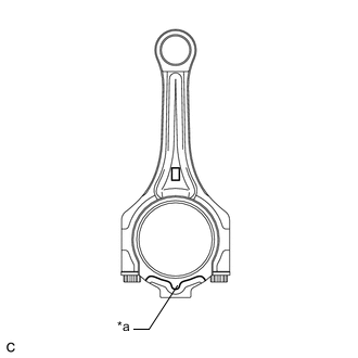
*a Front Mark Check that the front marks on the connecting rod sub-assembly and connecting rod cap are aligned.
Tech Tips
When installing the connecting rod caps, the marks on bank 1 cylinders (1, 3, 5, 7) face towards the front of the engine and bank 2 cylinders (2, 4, 6, 8) face towards the rear of the engine.
-
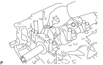
Remove the 2 connecting rod bolts.
-
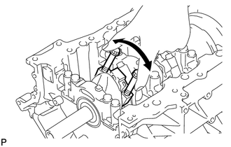
Using the 2 removed connecting rod bolts, remove the connecting rod cap and connecting rod bearing by wiggling the connecting rod cap right and left.
Tech Tips
Keep the connecting rod bearing installed to the connecting rod cap.
-
Clean the crank pin and connecting rod bearing.
Note
Check the crank pin and connecting rod bearing for pitting and scratches.
-
Lay a strip of Plastigage on the crank pin.
-
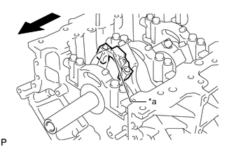
*a Front Mark 
Engine Front Check that the front mark of the connecting rod cap is facing the front of the engine.
-
Apply a light coat of engine oil to the threads and under the heads of the connecting rod bolts.
-
Install the connecting rod bolts.
Note
Do not turn the crankshaft during the procedure.
Tech Tips
The connecting rod bolts are tightened in 2 progressive steps.
-
Step 1:
-
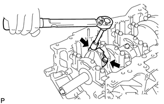
Install and alternately tighten the connecting rod bolts of each connecting rod cap in several steps.
- Torque:
- 40 N*m { 408 kgf*cm, 30 ft.*lbf }
-
-
Step 2:
-
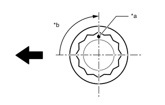
*a Paint Mark *b 90° Engine Front Mark the front side of each connecting rod bolt with paint.
-
Tighten the connecting rod bolts another 90° as shown in the illustration.
-
-
Check that the paint marks are now at a 90° angle to the front.
Note
Do not turn the crankshaft.
-
Remove the 2 connecting rod bolts and connecting rod cap.
-
Measure the Plastigage at its widest point.
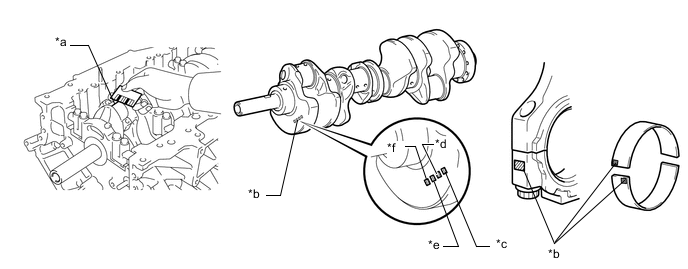
*a Plastigage *b Number Mark *c No. 1 *d No. 2 *e No. 3 *f No. 4 Standard Oil Clearance 0.037 to 0.062 mm (0.00146 to 0.00244 in.) Maximum Oil Clearance 0.080 mm (0.00315 in.) If the oil clearance is more than the maximum, replace the connecting rod bearings. If necessary, inspect the crankshaft.
Tech Tips
-
If replacing a connecting rod bearing, select a new one with the same number as marked on the connecting rod cap. There are 4 size of standard connecting rod bearings, marked 1, 2, 3 or 4 accordingly.
-
Select the correct connecting rod bearing by adding together the number marks imprinted on the connecting rod big end and crankshaft pin.
Connecting rod "1" + Crankshaft pin "2" = 3 (Use bearing "3")
Standard Connecting Rod Bearing Center Wall Thickness Mark Specified Condition 2 1.483 to 1.486 mm (0.0584 to 0.0585 in.) 3 1.486 to 1.489 mm (0.0585 to 0.0586 in.) 4 1.489 to 1.492 mm (0.0586 to 0.0587 in.) 5 1.492 to 1.495 mm (0.0587 to 0.0589 in.) 6 1.495 to 1.498 mm (0.0589 to 0.0590 in.) 7 1.498 to 1.501 mm (0.0590 to 0.0591 in.) Standard Connecting Rod Diameter Mark Specified Condition 1 51.000 to 51.006 mm (2.00787 to 2.00811 in.) 2 51.007 to 51.012 mm (2.00815 to 2.00834 in.) 3 51.013 to 51.018 mm (2.00838 to 2.00858 in.) 4 51.019 to 51.024 mm (2.00862 to 2.00881 in.) Standard Crankshaft Pin Diameter Mark Specified Condition 1 47.995 to 48.000 mm (1.8896 to 1.8898 in.) 2 47.989 to 47.994 mm (1.8893 to 1.8895 in.) 3 47.982 to 47.988 mm (1.8891 to 1.8893 in.) -
-
Completely remove the Plastigage.
-
Perform the inspection for each cylinder.
-
-
REMOVE PISTON SUB-ASSEMBLY WITH CONNECTING ROD
-
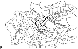
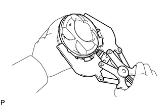
Using a ridge reamer, remove all the carbon from the top of the cylinder.
-
Push the piston, connecting rod sub-assembly and connecting rod bearing through the top of the cylinder block sub-assembly.
Tech Tips
-
Keep each connecting rod bearing, connecting rod and connecting rod cap together.
-
Arrange the removed parts in such a way that they can be reinstalled to their original locations.
-
-
-
REMOVE CONNECTING ROD BEARING
-
Remove the connecting rod bearings from the connecting rod and connecting rod cap.
Tech Tips
Arrange the removed parts in such a way that they can be reinstalled to their original locations.
-
-
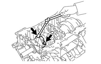
INSPECT CRANKSHAFT THRUST CLEARANCE
-
Using a dial indicator, measure the crankshaft thrust clearance while prying the crankshaft back and forth with a screwdriver.
Standard Thrust Clearance 0.020 to 0.220 mm (0.000787 to 0.00866 in.) Maximum Thrust Clearance 0.30 mm (0.0118 in.) If the crankshaft thrust clearance is more than the maximum, replace the thrust washers as a set. If necessary, replace the crankshaft.
Standard Thrust Washer Thickness 2.44 to 2.49 mm (0.0961 to 0.0980 in.)
-
-
REMOVE CRANKSHAFT
-
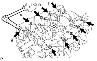
Uniformly loosen and remove the 10 bolts and 10 seal washers in several steps in the order shown in the illustration.
-
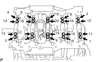
Uniformly loosen the 20 crankshaft bearing cap set bolts in several steps in the order shown in the illustration.
-
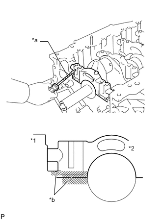
*1 Cylinder Block Sub-assembly *2 Crankshaft Bearing Cap *a Protective Tape *b Contact Surface Using a screwdriver, pry out the crankshaft bearing caps. Remove the 5 crankshaft bearing caps and lower crankshaft bearings.
Note
-
Pry up the main bearing caps gradually and evenly in turns.
-
Be careful not to damage the contact surfaces between the cylinder block sub-assembly and crankshaft bearing caps.
Tech Tips
Tape the screwdriver tip before use.
-
-
Remove the crankshaft.
-
-
REMOVE CRANKSHAFT THRUST WASHER SET
-
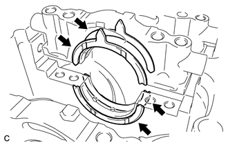
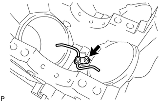
Remove the crankshaft thrust washer set from the No. 2 journal position of the cylinder block sub-assembly.
-
-
REMOVE CRANKSHAFT BEARING
-
Remove the upper crankshaft bearings and lower crankshaft bearings.
Tech Tips
Arrange the removed parts in such a way that they can be reinstalled to their original locations.
-
-
REMOVE PISTON RING SET
-
Using a piston ring expander, remove the No. 1 compression ring and No. 2 compression ring
Tech Tips
Arrange the removed parts in such a way that they can be reinstalled to their original locations.
-
Using a piston ring expander, remove the oil ring.
-
Remove the oil ring expander by hand.
-
-
REMOVE PISTON SUB-ASSEMBLY WITH PIN
-
Remove the connecting rod sub-assembly from the piston.
-
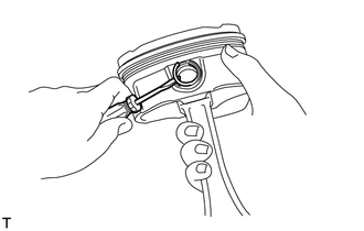
Using a screwdriver, pry out the piston pin hole snap ring from the piston.
-
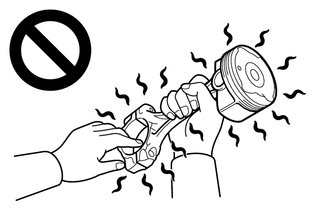
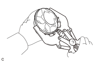
Gradually heat the piston to approximately 80°C (176°F).
CAUTION:
-
Do not touch the piston without wearing protective gloves, as it may get very hot during operation.
-
Be sure to wear protective gloves to avoid burns.
-
-
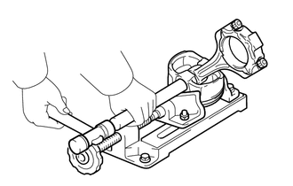
Using a brass bar and a plastic hammer, lightly tap out the piston pin and remove the connecting rod sub-assembly.
Tech Tips
-
The piston and piston pin are a matched set.
-
Arrange the removed parts in such a way that they can be installed to their original locations.
-
-
-
Clean the piston.
-
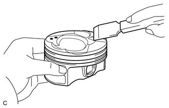
Using a gasket scraper, remove any carbon from the piston top.
-
Using a groove cleaning tool or broken ring, clean the piston ring grooves.
-
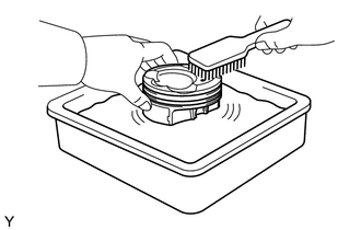
Using solvent and a brush, thoroughly clean the piston.
Note
Do not use a wire brush.
-
-
-
REMOVE NO. 1 OIL NOZZLE SUB-ASSEMBLY
-
Using a 5 mm hexagon socket wrench, remove the 4 bolts and 4 No. 1 oil nozzle sub-assemblies.
-
-
REMOVE STUD BOLT
Tech Tips
If a stud bolt is deformed or its threads are damaged, replace it.
-
Using an E8 "TORX" socket wrench, remove the stud bolts.
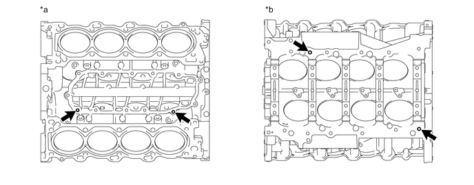
*a Upper Side *b Lower Side
-