CYLINDER HEAD DISASSEMBLY

CAUTION / NOTICE / HINT
The necessary procedures (adjustment, calibration, initialization, or registration) that must be performed after parts are removed, installed, or replaced during the cylinder head sub-assembly disassembly/reassembly are shown below.
| Replacement Part or Procedure | Necessary Procedure | Effect/Inoperative when not Performed | Link |
|---|---|---|---|
| Disconnect cable from negative battery terminal | Memorize steering angle neutral point | LKA/LDA system | |
| Pre-collision system | |||
| Parking assist monitor system | |||
| Steering sensor zero point calibration | Variable gear ratio steering system | ||
|
Inspection After Repair |
|
w/ Canister Pump Module: Click here w/o Canister Pump Module: Click here |
| Engine assembly | Inspection After Repair | ||
|
|
||
| Automatic transmission assembly |
|
|
for Initialization: Click here for Registration: Click here |
| Automatic transmission fluid | ATF thermal degradation estimate reset | The value of the Data List item "ATF Thermal Degradation Estimate" is not estimated correctly. | |
| Parts between the steering wheel and tires have been removed/installed, replaced or adjusted | Perform Actuator Angle Neutral Point Calibration and Initialization |
|
*1: New automatic transmission's compensation code.
*2: w/ Canister Pump Module
Tech Tips
-
Use the same procedure for the Bank 2 side and Bank 1 side.
-
The following procedure is for the Bank 1 side.
PROCEDURE
-
REMOVE VALVE ADJUSTING SHIM
-
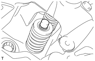
Remove the 16 valve adjusting shims from the cylinder head LH.
Tech Tips
Arrange the removed parts in such a way that they can be installed to their original locations.
-
-
REMOVE LH CYLINDER HEAD INTAKE VALVE
-
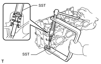
Using SST, compress the LH cylinder head intake valve and remove the 16 LH cylinder head valve spring retainer locks.
- SST
- 09202-70020 ( 09202-00010, 09202-01010, 09202-01020 )
-
Remove the 8 LH cylinder head valve spring retainers, 8 LH cylinder head intake valve compression springs and 8 LH cylinder head intake valves from the cylinder head LH.
Tech Tips
Arrange the removed parts in such a way that they can be installed to their original locations.
-
-
REMOVE LH CYLINDER HEAD EXHAUST VALVE
-
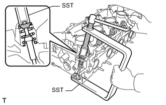
Using SST, compress the LH cylinder head exhaust valve and remove the 16 LH cylinder head valve spring retainer locks.
- SST
- 09202-70020 ( 09202-00010, 09202-01010, 09202-01020 )
-
Remove the 8 LH cylinder head valve spring retainers, 8 LH cylinder head exhaust valve compression springs and 8 LH cylinder head exhaust valves from the cylinder head LH.
Tech Tips
Arrange the removed parts in such a way that they can be installed to their original locations.
-
-
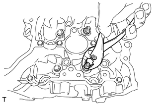
REMOVE LH CYLINDER HEAD INTAKE VALVE STEM OIL SEAL
-
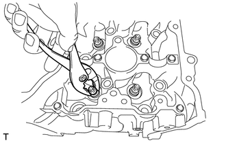
Using pliers, remove the 8 LH cylinder head intake valve stem oil seals.
-
-
REMOVE LH CYLINDER HEAD EXHAUST VALVE STEM OIL SEAL
-
Using pliers, remove the 8 LH cylinder head exhaust valve stem oil seals.
-
-
REMOVE LH CYLINDER HEAD VALVE SPRING SEAT
-
Using compressed air and a magnet hand, remove the 16 LH cylinder head valve spring seats from the cylinder head LH by blowing air onto them.
Tech Tips
Arrange the removed parts in such a way that they can be installed to their original locations.
-
-
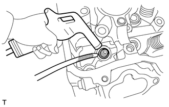
REMOVE NO. 1 STRAIGHT SCREW PLUG
-
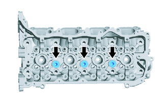
Using a 10 mm hexagon socket wrench, remove the 6 No. 1 straight screw plugs and 6 screw plug gaskets.
Note
If coolant leaks from a No. 1 straight screw plug or the No. 1 straight screw plug is corroded, replace it.
-
-
REMOVE NO. 2 STRAIGHT SCREW PLUG
-
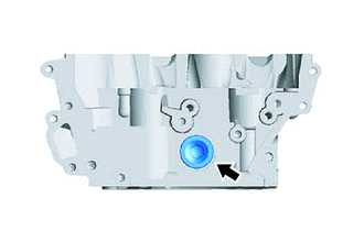
Using a 14 mm hexagon socket wrench, remove the 2 No. 2 straight screw plugs and 2 screw plug gaskets.
Note
If coolant leaks from a No. 2 straight screw plug or the No. 2 straight screw plug is corroded, replace it.
-
-
REMOVE STUD BOLT
Note
If a stud bolt is deformed or the threads are damaged, replace it.
-
Using E6 and E8 "TORX" socket wrenches, remove the stud bolts.
-