FUEL INJECTOR(for Port Injection) REMOVAL

CAUTION / NOTICE / HINT
The necessary procedures (adjustment, calibration, initialization, or registration) that must be performed after parts are removed, installed, or replaced during the port fuel injector assembly removal/installation are shown below.
| Replacement Part or Procedure | Necessary Procedure | Effect/Inoperative when not Performed | Link |
|---|---|---|---|
| Disconnect cable from negative battery terminal | Memorize steering angle neutral point | LKA /LDA system | |
| Pre-collision system | |||
| Parking assist monitor system | |||
| Steering sensor zero point calibration | Variable gear ratio steering system | ||
| Replacement of port fuel injector assembly | Inspection After Repair |
|
|
CAUTION:
-
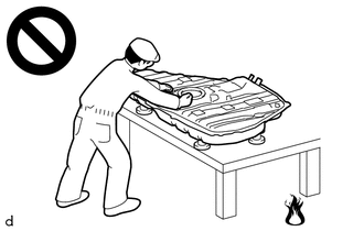
Never perform work on fuel system components near any possible ignition sources.
-
Vaporized fuel could ignite, resulting in a serious accident.
-
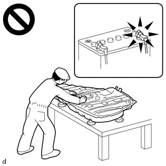
Do not perform work on fuel system components without first disconnecting the cable from the negative (-) battery terminal.
-
Sparks could cause vaporized fuel to ignite, resulting in a serious accident.
PROCEDURE
-
DISCHARGE FUEL SYSTEM PRESSURE
-
PRECAUTION
Note
After turning the engine switch off, waiting time may be required before disconnecting the cable from the negative (-) battery terminal. Therefore, make sure to read the disconnecting the cable from the negative (-) battery terminal notices before proceeding with work.
-
DISCONNECT CABLE FROM NEGATIVE BATTERY TERMINAL
Note
When disconnecting the cable, some systems need to be initialized after the cable is reconnected.
-
REMOVE NO. 2 FUEL TUBE SUB-ASSEMBLY
Note
Remove any dirt or foreign matter on the fuel tube connector and fuel pipe before performing this work.
-
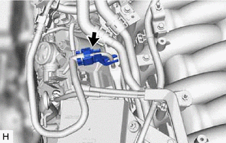
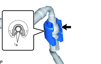
Remove the fuel pipe clamp from fuel tube connector.
-
Check that there is no dirt or other foreign matter around the fuel tube connector before disconnecting it. Clean the joint if necessary.
-
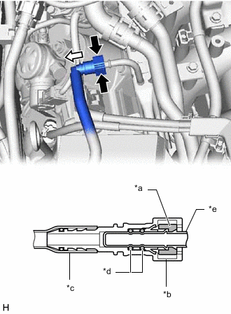
*a Retainer *b Fuel Tube Connector *c Nylon Tube *d O-ring *e Fuel Pipe 
Pinch 
Pull Disconnect the No. 2 fuel tube sub-assembly from the fuel delivery pipe sub-assembly.
-
*a Claw Detach the 2 claws to remove the No. 2 fuel pipe clamp.
Note
Do not reuse the No. 2 fuel pipe clamp.
-
Remove the No. 2 fuel tube sub-assembly from the fuel pipe (for Vehicle side).
-
-
REMOVE THROTTLE BODY WITH MOTOR ASSEMBLY
-
REMOVE RADIATOR SUPPORT TO CROSS MEMBER BRACE SUB-ASSEMBLY LH
-
REMOVE RADIATOR SUPPORT TO CROSS MEMBER BRACE SUB-ASSEMBLY RH
-
REMOVE AIR CLEANER WITH ELEMENT ASSEMBLY RH
-
REMOVE AIR CLEANER WITH ELEMENT ASSEMBLY LH
-
REMOVE INTAKE AIR CONNECTOR PIPE
-
REMOVE INTAKE AIR SOUND CREATOR
-
REMOVE NO. 2 INTAKE AIR CONNECTOR PIPE
-
REMOVE AIR CLEANER HOSE CLAMP
-
REMOVE NO. 2 ENGINE UNDER COVER ASSEMBLY
-
DISENGAGE ENGINE WIRE
-
REMOVE INJECTOR DRIVER
-
REMOVE INJECTOR DRIVER BRACKET
-
REMOVE WATER BY-PASS PIPE SUB-ASSEMBLY
-
REMOVE PURGE VALVE (PURGE VSV)
-
REMOVE FUEL TUBE SUB-ASSEMBLY
-
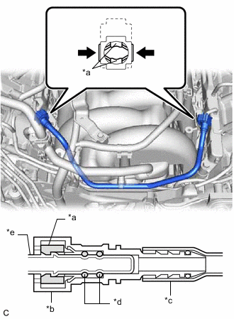
*a Retainer *b Fuel Tube Connector *c Nylon Tube *d O-ring *e Fuel Pipe Pinch Remove the fuel tube sub-assembly from the fuel delivery pipe sub-assembly and No. 2 fuel delivery pipe sub-assembly.
Note
Remove any dirt or foreign matter on the fuel tube connector and fuel pipe before performing this work.
-
-
REMOVE NO. 2 FUEL DELIVERY PIPE SUB-ASSEMBLY (for Bank 1)
-
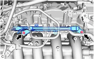
Remove the 2 bolts and No. 2 fuel delivery pipe sub-assembly with the port fuel injector assemblies.
Note
Be careful not to drop the port fuel injector assemblies when removing the No. 2 fuel delivery pipe sub-assembly.
-
-
REMOVE FUEL DELIVERY PIPE SUB-ASSEMBLY (for Bank 2)
-
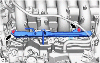
Remove the 2 bolts and fuel delivery pipe sub-assembly with the port fuel injector assemblies.
Note
Be careful not to drop the port fuel injector assemblies when removing the fuel delivery pipe sub-assembly.
-
-
REMOVE NO. 1 DELIVERY PIPE SPACER
-
Remove the 4 No. 1 delivery pipe spacers from the intake air surge tank assembly.
-
-
REMOVE INJECTOR VIBRATION INSULATOR
-
Remove the 8 injector vibration insulators from the intake air surge tank assembly.
-
-
REMOVE PORT FUEL INJECTOR ASSEMBLY
-
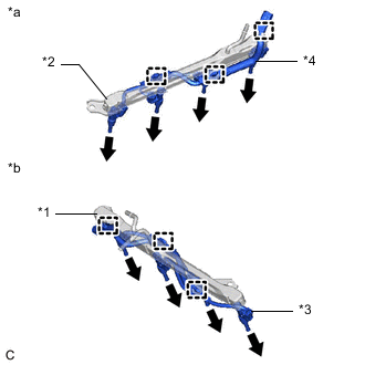
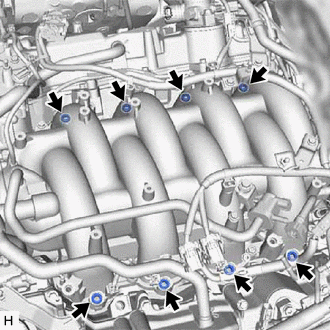
*1 Fuel Delivery Pipe Sub-assembly *2 No. 2 Fuel Delivery Pipe Sub-assembly *3 No. 6 Engine Wire *4 No. 7 Engine Wire *a for Bank 1 *b for Bank 2 Disengage the 3 clamps and disconnect the No. 6 engine wire from the fuel delivery pipe sub-assembly.
-
Disengage the 3 clamps and disconnect the No. 7 engine wire from the No. 2 fuel delivery pipe sub-assembly.
-
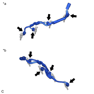
Remove the 8 port fuel injector assemblies from the fuel delivery pipe sub-assembly and No. 2 fuel delivery pipe sub-assembly.
Note
If the port fuel injector assemblies are to be reused, reinstall them to the same cylinder they were removed from.
-
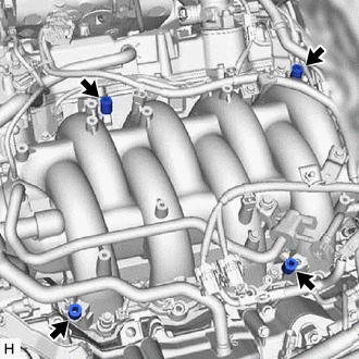
*a for Bank 1 *b for Bank 2 Disconnect the 8 port fuel injector assembly connectors.
-
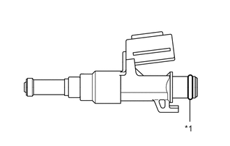
*1 O-ring Remove the O-ring from each port fuel injector assembly.
-
For reinstallation, attach a tag or label with the corresponding cylinder number to each port fuel injector assembly.
Note
Protect the port fuel injector assemblies by covering them with plastic bags.
-