ENGINE UNIT REMOVAL

CAUTION / NOTICE / HINT
The necessary procedures (adjustment, calibration, initialization, or registration) that must be performed after parts are removed and installed, or replaced during the engine unit removal/installation are shown below.
| Replacement Part or Procedure | Necessary Procedure | Effect/Inoperative when not Performed | Link |
|---|---|---|---|
| Disconnect cable from negative battery terminal | Memorize steering angle neutral point | LKA/LDA system | |
| Pre-collision system | |||
| Parking assist monitor system | |||
| Steering sensor zero point calibration | Variable gear ratio steering system | ||
|
Inspection After Repair |
|
w/ Canister Pump Module: Click here w/o Canister Pump Module: Click here |
| Engine assembly | Inspection After Repair | ||
|
|
||
| Automatic transmission assembly |
|
|
for Initialization: Click here for Registration: Click here |
| Automatic transmission fluid | ATF thermal degradation estimate reset | The value of the Data List item "ATF Thermal Degradation Estimate" is not estimated correctly. | |
| Parts between the steering wheel and tires have been removed/installed, replaced or adjusted | Perform Actuator Angle Neutral Point Calibration and Initialization |
|
*1: New automatic transmission's compensation code.
*2: w/ Canister Pump Module
PROCEDURE
-
INSTALL ENGINE TO ENGINE STAND
-
Install the engine assembly to an engine stand with the bolts.
-
-
REMOVE NO. 1 ENGINE HANGER
-
Remove the 2 bolts and 2 No. 1 engine hangers.
-
-
REMOVE ENGINE WIRE
-
Remove the engine wire from the engine assembly.
-
-
DISCONNECT NO. 5 ENGINE WIRE
-
REMOVE FRONT NO. 1 ENGINE MOUNTING BRACKET LH
-
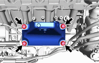
Remove the 4 bolts and front No. 1 engine mounting bracket LH.
-
-
REMOVE FRONT NO. 1 ENGINE MOUNTING BRACKET RH
-
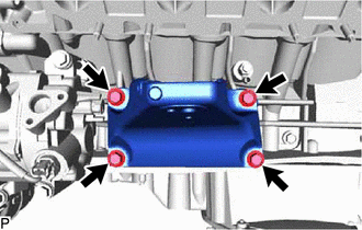
Remove the 4 bolts and front No. 1 engine mounting bracket RH.
-
-
REMOVE NO. 4 V-BANK COVER BRACKET SUB-ASSEMBLY
-
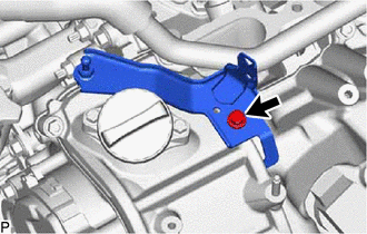
Remove the bolt and No. 4 V-bank cover bracket sub-assembly.
-
-
REMOVE NO. 3 V-BANK COVER BRACKET SUB-ASSEMBLY
-
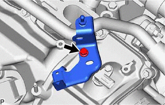
Remove the bolt and No. 3 V-bank cover bracket sub-assembly.
-
-
REMOVE WIRE HARNESS CLAMP BRACKET
-
Remove the 2 V-bank cover brackets, 2 injector driver brackets and wire harness clamp brackets.
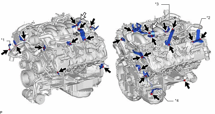
*1 Intake Air Connector Bracket *2 No. 1 Intake Air Connector Bracket *3 No. 2 Intake Air Connector Bracket *4 Crank Position Sensor Bracket 
Bolt 
V-bank Cover Bracket 
Injector Driver Bracket - - -
Remove the bolt and crank position sensor bracket.
-
Remove the bolt and intake air connector bracket.
-
Remove the 2 bolts and No. 1 intake air connector bracket.
-
Remove the bolt and No. 2 intake air connector bracket.
-
Remove the 2 bolts and 2 V-bank cover brackets.
-
Remove the 4 bolts and 2 injector driver brackets.
-
Remove the 15 bolts and 13 wire harness clamp brackets.
-
-
REMOVE THROTTLE BODY WITH MOTOR ASSEMBLY
-
REMOVE INJECTOR DRIVER
-
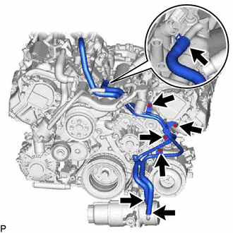
REMOVE WATER BY-PASS PIPE SUB-ASSEMBLY
-
Slide the clip and disconnect the No. 3 water by-pass hose from the water by-pass pipe sub-assembly.
-
Slide the clip and disconnect the water by-pass hose from the water by-pass pipe sub-assembly.
-
Slide the clip and disconnect the No. 5 water by-pass hose from the water by-pass pipe sub-assembly.
-
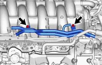
Remove the 2 bolts and water by-pass pipe sub-assembly from the intake air surge tank assembly.
-
-
REMOVE PURGE VSV
-
DISCONNECT VACUUM HOSE SUB-ASSEMBLY
-
REMOVE FUEL VAPOR FEED HOSE
-
REMOVE NO. 2 PCV HOSE
-
Slide the clip and disconnect the No. 2 PCV hose from the cylinder head cover sub-assembly.
-
-
REMOVE NO. 3 PCV HOSE
-
Slide the clip and disconnect the No. 3 PCV hose from the cylinder head cover sub-assembly LH.
-
-
DISCONNECT PCV HOSE
-
REMOVE FUEL TUBE SUB-ASSEMBLY
-
REMOVE NO. 2 FUEL DELIVERY PIPE SUB-ASSEMBLY
-
REMOVE FUEL DELIVERY PIPE SUB-ASSEMBLY
-
REMOVE NO. 1 DELIVERY PIPE SPACER
-
REMOVE INJECTOR VIBRATION INSULATOR
-
REMOVE PORT FUEL INJECTOR ASSEMBLY
-
DISCONNECT NO. 1 FUEL PIPE SUB-ASSEMBLY
-
REMOVE INTAKE AIR SURGE TANK ASSEMBLY
-
REMOVE NO. 1 ENGINE COVER SUB-ASSEMBLY
-
REMOVE NO. 3 COVER SUB-ASSEMBLY
-
REMOVE NO. 1 FUEL PIPE SUB-ASSEMBLY
-
REMOVE NO. 3 FUEL PIPE SUB-ASSEMBLY
-
REMOVE NO. 2 FUEL PIPE SUB-ASSEMBLY
-
REMOVE FUEL PUMP WITH SEAL SUB-ASSEMBLY (for Bank 1)
-
REMOVE FUEL PUMP WITH SEAL SUB-ASSEMBLY (for Bank 2)
-
REMOVE NO. 2 ENGINE COVER SUB-ASSEMBLY LH
-
REMOVE NO. 4 FUEL PIPE SUB-ASSEMBLY
-
REMOVE CASE SEPARATOR
-
REMOVE FUEL DELIVERY PIPE LH
-
REMOVE FUEL DELIVERY PIPE RH
-
REMOVE DIRECT FUEL INJECTOR ASSEMBLY
-
REMOVE FUEL INJECTOR SEAL
-
REMOVE NO. 5 ENGINE WIRE
-
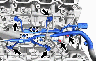
Disconnect the 4 knock sensor connectors.
-
Detach the 3 clamps.
-
Remove the 2 bolts and No. 5 engine wire.
-
-
REMOVE NO. 4 ENGINE COVER SUB-ASSEMBLY
-
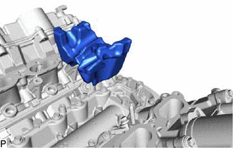
Remove the No. 4 engine cover sub-assembly.
-
-
REMOVE NO. 2 IDLER PULLEY SUB-ASSEMBLY
-
Remove the bolt and No. 2 idler pulley sub-assembly.
-
-
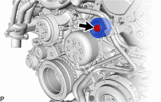
REMOVE OIL PUMP DRIVE SHAFT PULLEY
-
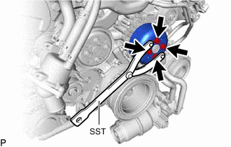
Using SST, hold the oil pump drive shaft pulley.
- SST
- 09960-10010
-
Remove the 4 bolts and oil pump drive shaft pulley.
-
-
REMOVE WATER PUMP PULLEY
-
REMOVE WATER INLET HOUSING
-
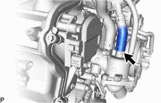
Slide the clip and disconnect the water inlet hose from the water inlet housing.
-
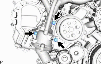
Remove the 3 bolts, water inlet housing and gasket.
-
-
REMOVE ENGINE OIL PRESSURE SWITCH ASSEMBLY
-
REMOVE ENGINE OIL TEMPERATURE SENSOR
-
REMOVE ENGINE OIL LEVEL SENSOR
-
REMOVE NO. 2 WATER BY-PASS PIPE SUB-ASSEMBLY
-
Slide the 3 clips and disconnect the No. 2 water by-pass pipe sub-assembly from the oil cooler and heat exchanger assembly.
-
Remove the 4 bolts and No. 2 water by-pass pipe sub-assembly.
-
-
REMOVE ENGINE COOLANT TEMPERATURE SENSOR
-
REMOVE KNOCK SENSOR
-
REMOVE IGNITION COIL ASSEMBLY