ENGINE ASSEMBLY REMOVAL
CAUTION / NOTICE / HINT
The necessary procedures (adjustment, calibration, initialization, or registration) that must be performed after parts are removed, installed, or replaced during the engine assembly removal/installation are shown below.
| Replacement Part or Procedure | Necessary Procedure | Effect/Inoperative when not Performed | Link |
|---|---|---|---|
| Disconnect cable from negative battery terminal | Memorize steering angle neutral point | LKA/LDA system | |
| Pre-collision system | |||
| Parking assist monitor system | |||
| Steering sensor zero point calibration | Variable gear ratio steering system | ||
|
Inspection After Repair |
|
w/ Canister Pump Module: Click here w/o Canister Pump Module: Click here |
| Engine assembly | Inspection After Repair | ||
|
|
||
| Automatic transmission assembly |
|
|
for Initialization: Click here for Registration: Click here |
| Automatic transmission fluid | ATF thermal degradation estimate reset | The value of the Data List item "ATF Thermal Degradation Estimate" is not estimated correctly. | |
| Parts between the steering wheel and tires have been removed/installed, replaced or adjusted | Perform Actuator Angle Neutral Point Calibration and Initialization |
|
*1: New automatic transmission's compensation code.
*2: w/ Canister Pump Module
CAUTION:
-
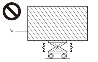
*a Heavy object exceeding the capacity of the engine lifter Because the weight of the engine with transmission assembly is extremely heavy, make sure to follow the work procedures described in the repair manual.
-
If work is not performed according to the procedures described in the repair manual, there is a danger that the engine lifter could drop and components could fall down.
-
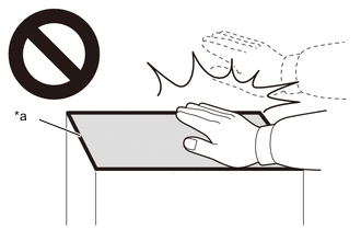
*a High temperature areas Do not touch the engine or exhaust manifold sub-assembly when they are hot.
-
Touching the engine or exhaust manifold sub-assembly when they are hot could result in burns.
-
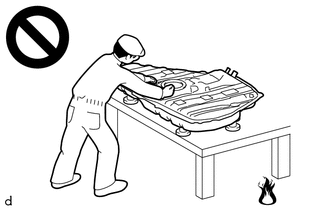
Never perform work on fuel system components near any possible ignition sources.
-
Vaporized fuel could ignite, resulting in a serious accident.
-
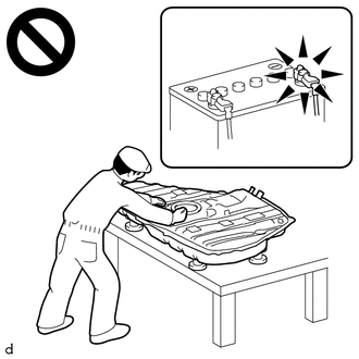
Do not perform work on fuel system components without first disconnecting the cable from the negative (-) battery terminal.
-
Sparks could cause vaporized fuel to ignite, resulting in a serious accident.
Note
When the oil cooler assembly (for air cooled type) has been removed/installed or the oil cooler hose sub-assembly has been disconnected/reconnected, check the engine oil level after warming up the engine oil to between 100°C (212°F) and 120°C (248°F) to open the thermostat between the engine and oil cooler assembly (for air cooled type).
PROCEDURE
-
PRECAUTION
Note
After turning the engine switch off, waiting time may be required before disconnecting the cable from the negative (-) battery terminal. Therefore, make sure to read the disconnecting the cable from the negative (-) battery terminal notices before proceeding with work.
-
REMOVE V-BANK COVER SUB-ASSEMBLY
-
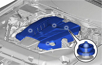
Hold the front of the V-bank cover sub-assembly and raise it to disengage the 2 front clips. Continue to raise the V-bank cover sub-assembly to disengage the 2 rear clips to remove the V-bank cover sub-assembly.
Note
Attempting to disengage both front and rear clips at the same time may cause the V-bank cover sub-assembly to break.
-
-
REMOVE RADIATOR SUPPORT TO FRAME SEAL LH
-
REMOVE RADIATOR SUPPORT TO FRAME SEAL RH
-
REMOVE LOWER RADIATOR AIR DEFLECTOR
-
RECOVER REFRIGERANT FROM REFRIGERATION SYSTEM
-
for HFC-134a(R134a):
-
for HFO-1234yf(R1234yf):
-
-
DISCHARGE FUEL SYSTEM PRESSURE
-
DISCONNECT CABLE FROM NEGATIVE BATTERY TERMINAL
-
PARKING LOCK FORCED RELEASE
-
ALIGN FRONT WHEELS FACING STRAIGHT AHEAD
-
SECURE STEERING WHEEL
-
REMOVE FRONT WHEELS
-
REMOVE NO. 1 ENGINE UNDER COVER ASSEMBLY
-
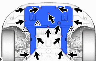
Remove the 15 screws, 3 clips and No. 1 engine under cover assembly.
-
-
REMOVE NO. 2 ENGINE UNDER COVER ASSEMBLY
-
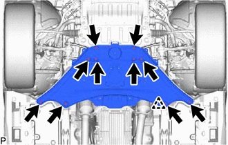
Remove the 10 bolts and No. 2 engine under cover assembly.
-
-
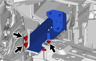
REMOVE STRUT BAR BRACKET SUPPORT SUB-ASSEMBLY
-
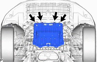
Remove the 4 bolts and strut bar bracket support sub-assembly.
-
-
DRAIN ENGINE OIL
-
DRAIN ENGINE COOLANT
-
DRAIN AUTOMATIC TRANSMISSION FLUID
-
REMOVE RADIATOR SUPPORT TO CROSSMEMBER BRACE SUB-ASSEMBLY LH
-
REMOVE RADIATOR SUPPORT TO CROSSMEMBER BRACE SUB-ASSEMBLY RH
-
REMOVE FENDER APRON BRACE SUB-ASSEMBLY LH (for LHD)
-
Remove the 2 bolts and fender apron brace sub-assembly LH.
-
-
REMOVE FENDER APRON BRACE SUB-ASSEMBLY LH (for RHD)
-
Detach the 2 claws and remove the center cowl top ventilator louver.
-
Remove the 2 bolts and fender apron brace sub-assembly LH.
-
-
REMOVE FENDER APRON BRACE SUB-ASSEMBLY RH (for LHD)
-
Detach the 2 claws and remove the center cowl top ventilator louver.
-
Detach the clamp and disconnect the No. 2 fuel tube from the fender apron brace sub-assembly RH.
-
Remove the 2 bolts and fender apron brace sub-assembly RH.
-
-
REMOVE FENDER APRON BRACE SUB-ASSEMBLY RH (for RHD)
-
Detach the clamp and disconnect the No. 2 fuel tube from the fender apron brace sub-assembly RH.
-
Remove the 2 bolts and fender apron brace sub-assembly RH.
-
-
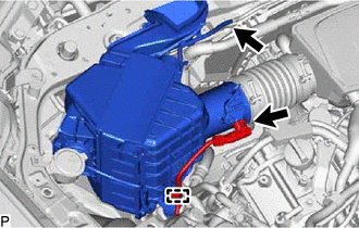
REMOVE AIR CLEANER WITH ELEMENT ASSEMBLY RH
-
Disconnect the mass air flow meter sub-assembly connector.
-
Disconnect the vacuum switching valve assembly connector.
-
Detach the 2 clamps and disconnect the wire harness clamp from the air cleaner with element assembly RH.
-
Disconnect the 2 vacuum hose sub-assemblies.
-
Pull out the 3 air cleaner with element assembly RH pins from the air cleaner support bracket and radiator upper support.
-
Loosen the hose clamp and remove the air cleaner with element assembly RH.
-
-
REMOVE AIR CLEANER WITH ELEMENT ASSEMBLY LH
-
Disconnect the mass air flow meter sub-assembly connector.
-
Detach the clamp and disconnect the wire harness clamp from the air cleaner with element assembly LH.
-
Disconnect the vacuum hose sub-assembly.
-
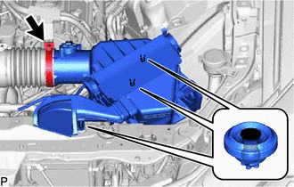
Pull out the 3 air cleaner with element assembly LH pins from the air cleaner support bracket and radiator upper support.
-
Loosen the hose clamp and remove the air cleaner with element assembly LH.
-
-
DISCONNECT NO. 2 PCV HOSE
-
DISCONNECT NO. 3 PCV HOSE
-
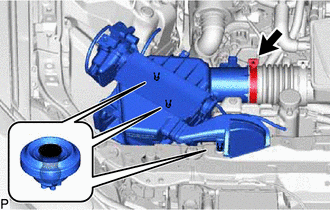
REMOVE AIR CLEANER HOSE ASSEMBLY
-
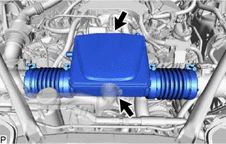
Loosen the 2 hose clamps and remove the air cleaner hose assembly.
-
-
REMOVE INTAKE AIR CONNECTOR PIPE
-
REMOVE INTAKE AIR SOUND CREATOR
-
REMOVE NO. 2 INTAKE AIR CONNECTOR PIPE
-
REMOVE RADIATOR RESERVE TANK ASSEMBLY
-
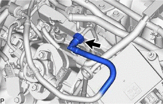
REMOVE RESERVE TANK OUTLET HOSE
-
DISCONNECT NO. 1 RADIATOR HOSE
-
REMOVE NO. 4 TRANSMISSION OIL COOLER HOSE
-
REMOVE WATER BY-PASS HOSE
-
DISCONNECT NO. 3 RADIATOR HOSE
-
REMOVE NO. 1 OIL COOLER INLET HOSE
-
REMOVE NO. 1 OIL COOLER OUTLET HOSE
-
DISCONNECT RADIATOR HOSE SUB-ASSEMBLY
-
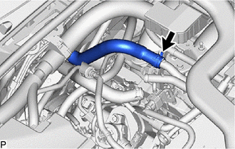
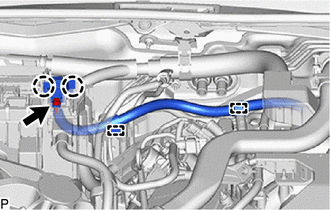
DISCONNECT HEATER WATER OUTLET HOSE
-
Slide the clip and disconnect the heater water outlet hose from the No. 3 water by-pass pipe.
-
-
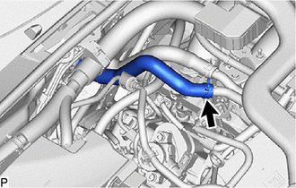
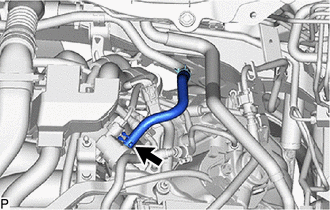
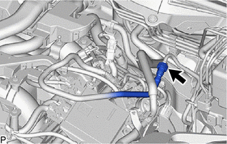
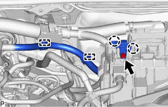
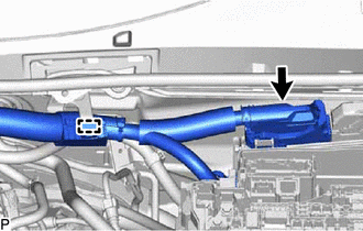
DISCONNECT HEATER WATER INLET HOSE
-
Slide the clip and disconnect the heater water inlet hose from the No. 3 water by-pass pipe.
-
-
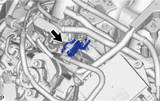
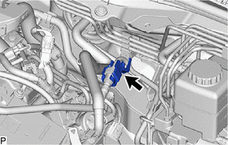
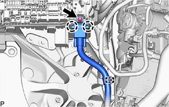
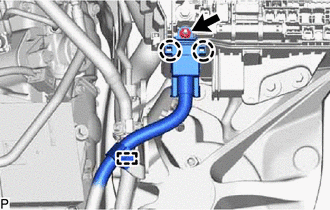
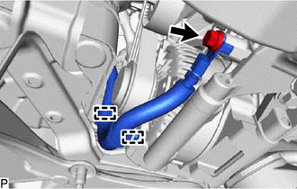
DISCONNECT NO. 1 FUEL VAPOR FEED HOSE
-
Slide the clip and disconnect the No. 1 fuel vapor feed hose from the purge valve (purge VSV).
-
-
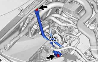
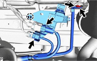
DISCONNECT NO. 2 FUEL TUBE SUB-ASSEMBLY
-
Remove the fuel pipe clamp from the No. 2 fuel tube sub-assembly.
-
Disconnect the No. 2 fuel tube sub-assembly.
-
-
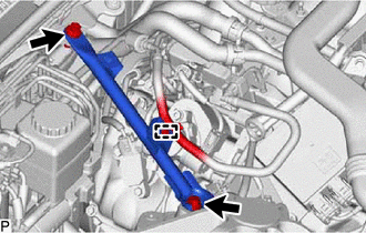
DISCONNECT FUEL TUBE SUB-ASSEMBLY
-
Remove the fuel pipe clamp from the fuel tube sub-assembly.
-
Disconnect the fuel tube sub-assembly.
-
-
DISCONNECT DISCHARGE HOSE SUB-ASSEMBLY
-
DISCONNECT SUCTION HOSE SUB-ASSEMBLY A
-
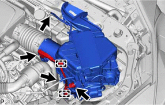
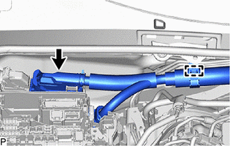
DISCONNECT NO. 2 ENGINE WIRE (for LHD)
Tech Tips
After disconnecting the wire harness, secure it with tape or equivalent to keep it out of the way.
-
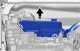
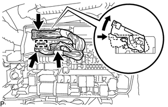
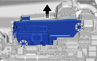
Remove the upper relay block cover from the No. 1 engine room relay block.
-
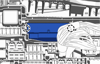
Detach the 2 clamps.
-
Remove the nut.
-
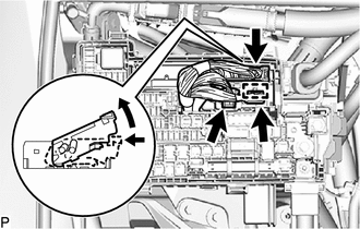
Detach the 2 claws and disconnect the No. 2 engine wire from the No. 1 engine room relay block.
-
-
DISCONNECT NO. 2 ENGINE WIRE (for RHD)
Tech Tips
After disconnecting the wire harness, secure it with tape or equivalent to keep it out of the way.
-
Remove the upper relay block cover from the No. 1 engine room relay block.
-
Detach the 2 clamps.
-
Remove the nut.
-
Detach the 2 claws and disconnect the No. 2 engine wire from the No. 1 engine room relay block.
-
-
DISCONNECT ENGINE WIRE (for LHD)
Tech Tips
After disconnecting the wire harness, secure it with tape or equivalent to keep it out of the way.
-
Detach the clamp.
-
Remove the nut.
-
Detach the 2 claws and disconnect the engine wire from the No. 1 engine room relay block.
-
Disconnect the ECM connector.
-
Detach the clamp.
-
Detach the 2 claws and disconnect the No. 1 semiconductor power integration ECU from the No. 1 engine room relay block.
-
Disconnect the 2 connectors.
-
Detach the claw and disconnect the junction connector.
-

Disconnect in this Derection Detach the 2 claws and disconnect the connector holder from the No. 1 engine room relay block.
-
-
DISCONNECT ENGINE WIRE (for RHD)
Tech Tips
After disconnecting the wire harness, secure it with tape or equivalent to keep it out of the way.
-
Detach the clamp.
-
Remove the nut.
-
Detach the 2 claws and disconnect the engine wire from the No. 1 engine room relay block.
-
Disconnect the ECM connector.
-
Detach the clamp.
-
Detach the 2 claws and disconnect the No. 1 semiconductor power integration ECU from the No. 1 engine room relay block.
-
Disconnect the 2 connectors.
-
Detach the claw and disconnect the junction connector.
-
Disconnect in this Derection Detach the 2 claws and disconnect the connector holder from the No. 1 engine room relay block.
-
-
DISCONNECT NO. 3 ENGINE ROOM WIRE (for LHD)
Tech Tips
After disconnecting the wire harness, secure it with tape or equivalent to keep it out of the way.
-
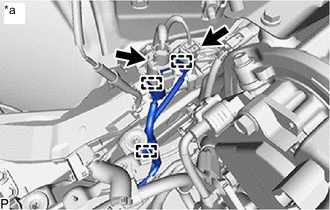
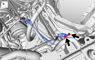
*a RH Side Disconnect the 2 connectors.
-
Detach the 3 clamps and disconnect the No. 3 engine room wire.
-
*a LH Side Remove the 2 bolts and disconnect the No. 3 engine room wire.
-
-
DISCONNECT NO. 3 ENGINE ROOM WIRE (for RHD)
Tech Tips
After disconnecting the wire harness, secure it with tape or equivalent to keep it out of the way.
-
Disconnect the 2 connectors.
-
Detach the claw and disconnect the No. 10 connector holder.
-
Remove the 2 bolts and disconnect the No. 3 engine room wire.
-
-
DISCONNECT NO. 3 ENGINE WIRE
Tech Tips
After disconnecting the wire harness, secure it with tape or equivalent to keep it out of the way.
-
Detach the 2 clamps.
-
Remove the bolt and disconnect the No. 3 engine wire from the generator assembly.
-
-
REMOVE FRONT BUMPER COVER
-
REMOVE NO. 2 FRONT BUMPER REINFORCEMENT SUB-ASSEMBLY
-
Remove the 6 nuts and No. 2 front bumper reinforcement sub-assembly.
-
-
REMOVE RADIATOR SUPPORT EXTENSION LH
-
REMOVE RADIATOR SUPPORT EXTENSION RH
-
REMOVE RADIATOR SUPPORT OPENING COVER
-
REMOVE REAR FRAME RAIL SUB-ASSEMBLY LH
-
Remove the 3 bolts, 2 nuts and rear frame rail sub-assembly LH.
-
-
REMOVE REAR FRAME RAIL SUB-ASSEMBLY RH
-
Remove the 3 bolts, 2 nuts and rear frame rail sub-assembly RH.
-
-
REMOVE REAR FLOOR SIDE MEMBER COVER LH
-
REMOVE REAR FLOOR SIDE MEMBER COVER RH
-
REMOVE FRONT FENDER SEAL LH
-
REMOVE FRONT FENDER SEAL RH
-
REMOVE FRONT FLOOR COVER LH
-
REMOVE FRONT FLOOR COVER RH
-
REMOVE FRONT SEAT ASSEMBLY
-
DISCONNECT HEATED OXYGEN SENSOR CONNECTOR
-
REMOVE HEATED OXYGEN SENSOR (for Bank 1)
-
REMOVE HEATED OXYGEN SENSOR (for Bank 2)
-
REMOVE FRONT CENTER FLOOR BRACE SUB-ASSEMBLY
-
REMOVE FRONT EXHAUST PIPE ASSEMBLY
-
REMOVE NO. 1 EXHAUST PIPE SUPPORT BRACKET SUB-ASSEMBLY
-
REMOVE FRONT NO. 1 FLOOR HEAT INSULATOR
-
REMOVE NO. 2 FUEL TANK PROTECTOR
-
REMOVE PROPELLER WITH CENTER BEARING SHAFT ASSEMBLY
-
REMOVE STEERING SLIDING WITH SHAFT YOKE SUB-ASSEMBLY
-
DISCONNECT FRONT SKID CONTROL SENSOR WIRE LH
-
DISCONNECT FRONT SKID CONTROL SENSOR WIRE RH
Tech Tips
Remove the RH side following the same procedure as for the LH side.
-
DISCONNECT FRONT HEIGHT CONTROL SENSOR SUB-ASSEMBLY LH
-
DISCONNECT FRONT HEIGHT CONTROL SENSOR SUB-ASSEMBLY RH
Tech Tips
Remove the RH side following the same procedure as for the LH side.
-
DISCONNECT DISC BRAKE CYLINDER ASSEMBLY LH
-
DISCONNECT DISC BRAKE CYLINDER ASSEMBLY RH
Tech Tips
Remove the RH side following the same procedure as for the LH side.
-
REMOVE FRONT DISC LH
-
REMOVE FRONT DISC RH
Tech Tips
Remove the RH side following the same procedure as for the LH side.
-
REMOVE FRONT DISC BRAKE DUST COVER LH
-
REMOVE FRONT DISC BRAKE DUST COVER RH
Tech Tips
Remove the RH side following the same procedure as for the LH side.
-
DISCONNECT TIE ROD ASSEMBLY LH
-
DISCONNECT TIE ROD ASSEMBLY RH
Tech Tips
Remove the RH side following the same procedure as for the LH side.
-
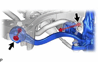
DISCONNECT FRONT STABILIZER LINK ASSEMBLY LH
-
DISCONNECT FRONT STABILIZER LINK ASSEMBLY RH
Tech Tips
Remove the RH side following the same procedure as for the LH side.
-
DISCONNECT STEERING KNUCKLE LH
-
DISCONNECT STEERING KNUCKLE RH
Tech Tips
Remove the RH side following the same procedure as for the LH side.
-
REMOVE STEERING KNUCKLE LH
-
Remove the 2 bolts, 2 nuts and steering knuckle LH.
-
-
REMOVE STEERING KNUCKLE RH
Tech Tips
Remove the RH side following the same procedure as for the LH side.
-
REMOVE ENGINE SIDE COVER LH
-
REMOVE ENGINE SIDE COVER RH
Tech Tips
Remove the RH side following the same procedure as for the LH side.
-
REMOVE REAR LOWER ARM MOUNTING REINFORCEMENT SUB-ASSEMBLY LH
-
REMOVE REAR LOWER ARM MOUNTING REINFORCEMENT SUB-ASSEMBLY RH
Tech Tips
Remove the RH side following the same procedure as for the LH side.
-
DISCONNECT NO. 2 PARKING LOCK RELEASE CABLE ASSEMBLY
-
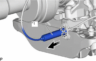
*1 Cover Disconnect Detach the 2 claws and disconnect the cover from the No. 2 parking lock release cable assembly as shown in the illustration.
-
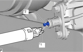
*1 Parking Lock Release Lever Assembly Cable End *2 No. 2 Parking Lock Release Cable Assembly Cable End Disconnect the parking lock release lever assembly cable end from the No. 2 parking lock release cable assembly cable end.
-
-
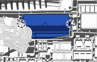
DISCONNECT NO. 2 GROUND WIRE
-
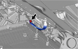
Remove the bolt and disconnect the No. 2 ground wire.
-
-
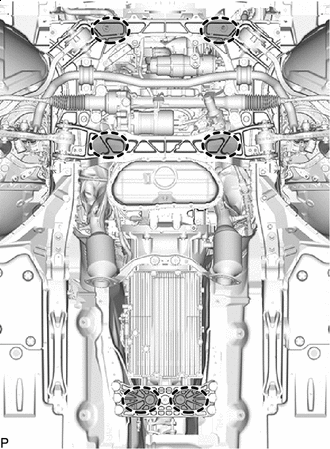
REMOVE ENGINE WITH TRANSMISSION ASSEMBLY
-

Place Wooden Block or Plate Attachments Set the engine on an engine lifter.
Note
-
Place wooden blocks or plate lift attachments so that the engine is level.
-
With the exception of installing the engine assembly to an engine stand or removing the engine assembly from an engine stand, do not perform any work on the engine while it is suspended, as doing so is dangerous.
-
Never install attachments to the oil pan of the engine assembly or transmission as doing so may deform the oil pan.
-
-
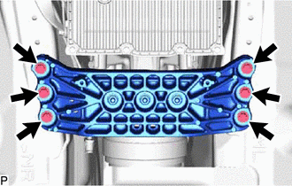
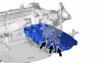
Remove the 6 bolts, and then separate the rear engine mounting member.
-

Bolt 
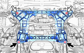
Nut Remove the 2 bolts and 2 nuts shown in the illustration.
-
Operate the engine lifter, then slowly remove the engine and transmission assembly from the vehicle.
Note
-
Make sure the engine is clear of all wiring and hoses.
-
While lowering the engine from the vehicle, do not allow it to contact the vehicle.
-
-
Attach an engine sling device and hang the engine with a chain block.
Note
Pay attention to the angle of the sling device as the engine assembly or engine hangers may be damaged or deformed if the angle is incorrect.
-
-
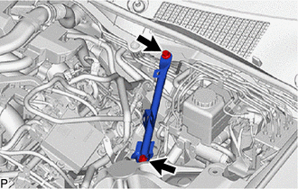
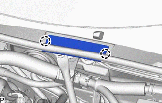
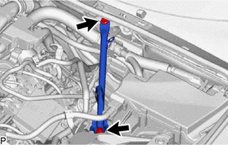
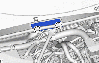
INSTALL NO. 1 ENGINE HANGER
-
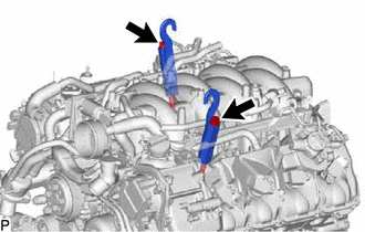
Install the 2 No. 1 engine hangers with the 2 bolts as shown in the illustration.
- Torque:
- 43 N*m { 438 kgf*cm, 32 ft.*lbf }
Tech Tips
No. 1 Engine Hanger 12081-38040 Bolt 90119-14120 -
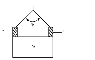
*1 No. 1 Engine Hanger *a Engine Assembly *b 50° or Less Attach an engine sling device and hang the engine with transmission assembly with a chain block.
Note
When hanging the engine assembly, make sure to hang it with the chains at an angle of 50° or less. Otherwise, the engine assembly or engine hangers may be damaged.
-
-
REMOVE ENGINE OIL LEVEL DIPSTICK GUIDE
-
REMOVE ENGINE MOUNTING DAMPER
-
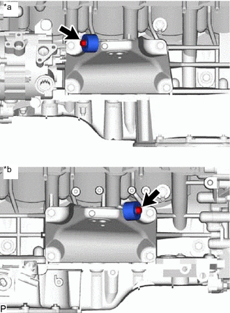
*a LH Side *b RH Side Remove the 2 bolts and 2 engine mounting dampers.
-
-
REMOVE NO. 1 EXHAUST MANIFOLD HEAT INSULATOR
-
REMOVE EXHAUST MANIFOLD SUB-ASSEMBLY RH
-
REMOVE EXHAUST MANIFOLD TO HEAD GASKET
-
REMOVE NO. 2 EXHAUST MANIFOLD HEAT INSULATOR
-
REMOVE EXHAUST MANIFOLD SUB-ASSEMBLY LH
-
REMOVE EXHAUST MANIFOLD TO HEAD GASKET LH
-
REMOVE NO. 3 EXHAUST MANIFOLD HEAT INSULATOR
-
REMOVE FAN AND GENERATOR V BELT
-
DISCONNECT WIRE HARNESS
-
REMOVE OIL COOLER TUBE
-
REMOVE COMPRESSOR ASSEMBLY WITH PULLEY
-
REMOVE GENERATOR ASSEMBLY
-
REMOVE STARTER ASSEMBLY
-
REMOVE DRIVE PLATE AND TORQUE CONVERTER ASSEMBLY SETTING BOLT
-
REMOVE AUTOMATIC TRANSMISSION ASSEMBLY
-
REMOVE REAR ENGINE MOUNTING MEMBER
Tech Tips
Perform this procedure only when replacement of the rear engine mounting member is necessary.
-
Remove the 3 nuts and rear engine mounting member from the rear engine mounting insulator.
-
-
REMOVE REAR ENGINE MOUNTING INSULATOR
-
REMOVE DRIVE PLATE AND RING GEAR SUB-ASSEMBLY
-
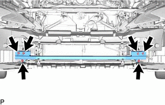
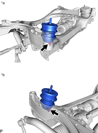
REMOVE FRONT FRAME CROSSMEMBER SUB-ASSEMBLY
-
*a LH Side *b RH Side Remove the 2 nuts and front suspension crossmember sub-assembly from the engine assembly.
-
-
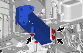
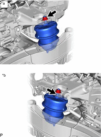
REMOVE FRONT ENGINE MOUNTING INSULATOR
Tech Tips
Perform this procedure only when replacement of the front engine mounting insulator is necessary.
-
*a LH Side *b RH Side Remove the 2 nuts and 2 front engine mounting insulators from the front suspension crossmember sub-assembly.
-
-
INSTALL ENGINE TO ENGINE STAND
-
Install the engine assembly to an engine stand.
Note
-
Pay attention to the angle of the sling device as the engine assembly or No. 1 engine hangers may be damaged or deformed if the angle is incorrect.
-
Do not perform any procedure while the engine assembly is suspended because doing so may cause the engine assembly to drop, resulting in injury. However, the engine assembly needs to be suspended when it is installed to or removed from an engine stand.
-
-
Remove the 2 bolts and 2 No. 1 engine hangers.
-
-
INSPECT EXHAUST MANIFOLD SUB-ASSEMBLY LH
-
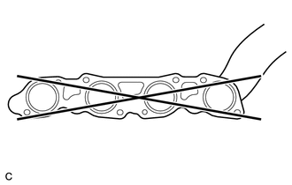
Using a precision straightedge and feeler gauge.
Check the surface which contacts the cylinder head LH for warpage.
Maximum Warpage 0.50 mm (0.0197 in.) If the warpage is more than the maximum, replace the exhaust manifold sub-assembly LH.
-
-
INSPECT EXHAUST MANIFOLD SUB-ASSEMBLY RH
-
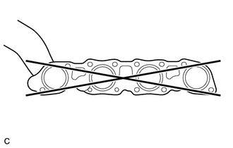
Using a precision straightedge and feeler gauge.
Check the surface which contacts the cylinder head sub-assembly for warpage.
Maximum Warpage 0.50 mm (0.0197 in.) If the warpage is more than the maximum, replace the exhaust manifold sub-assembly RH.
-