CYLINDER HEAD GASKET INSTALLATION
CAUTION / NOTICE / HINT
Tech Tips
Perform "Inspection After Repairs" after replacing the cylinder head sub-assembly or cylinder head LH.
-
w/ Canister Pump Module:
-
w/o Canister Pump Module:
PROCEDURE
-
INSPECT CYLINDER HEAD SET BOLT
-
INSTALL CYLINDER HEAD GASKET
-
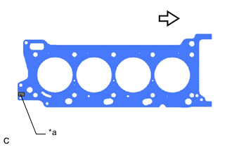
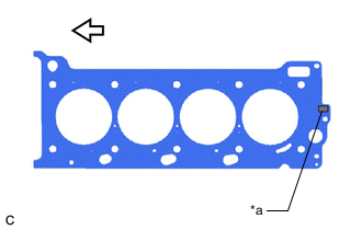
*a Lot No. 
Engine Front Place a new cylinder head gasket on the cylinder block sub-assembly with the Lot No. stamp facing upward.
Note
-
Be sure to place the gasket in the correct orientation.
-
Gently lower the cylinder head sub-assembly in order not to damage the cylinder head gasket with the bottom of the cylinder head sub-assembly.
-
-
-
INSTALL CYLINDER HEAD SUB-ASSEMBLY
Tech Tips
Perform "Inspection After Repairs" after replacing the cylinder head sub-assembly.
-
w/ Canister Pump Module:
-
w/o Canister Pump Module:
-
Place the cylinder head sub-assembly on the cylinder block sub-assembly.
Note
-
Clean all contact surfaces.
-
Inspect and clean each cylinder head set bolt and bolt hole.
-
Gently place the cylinder head sub-assembly in order not to damage the cylinder head gasket with the bottom part of the cylinder head sub-assembly.
-
-
Apply a light coat of engine oil to the threads and under the heads of the cylinder head set bolts.
Tech Tips
The cylinder head set bolts are tightened in 3 progressive steps.
-
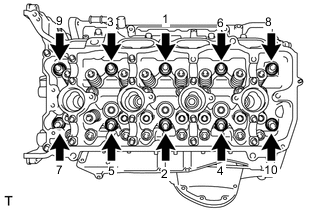
Step 1:
-
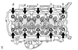
Using a 10 mm bi-hexagon wrench, install and uniformly tighten the 10 cylinder head set bolts with the plate washers in several steps in the order shown in the illustration.
- Torque:
- 36 N*m { 367 kgf*cm, 27 ft.*lbf }
-
-
Step 2:
-
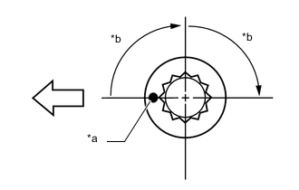
*a Paint Mark *b 90° Engine Front Mark each cylinder head set bolt head with paint as shown in the illustration.
-
Tighten the cylinder head set bolts another 90° in the order shown in step 1.
-
-
Step 3:
-
Tighten the cylinder head set bolts by an additional 90° in the order shown in step 1.
-
Check that the paint marks are now facing rearward.
-
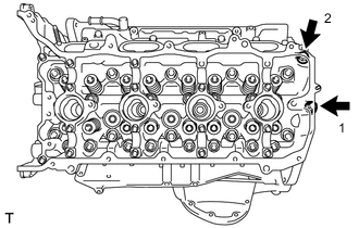
-
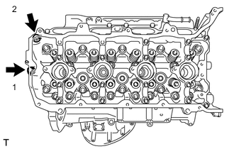
Install the 2 cylinder head set bolts in the order shown in the illustration.
- Torque:
- 21 N*m { 214 kgf*cm, 15 ft.*lbf }
-
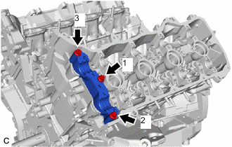
Place the camshaft housing RH on the cylinder head sub-assembly.
-
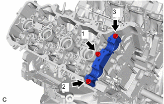
Temporarily tighten the 3 bolts in the order shown in the illustration.
- Torque:
- 10 N*m { 102 kgf*cm, 7 ft.*lbf }
-
Fully tighten the 3 bolts in the order shown in the illustration.
- Torque:
- 24 N*m { 245 kgf*cm, 18 ft.*lbf }
-
-
INSTALL NO. 2 CYLINDER HEAD GASKET
-
*a Lot No. Engine Front Place a new No. 2 cylinder head gasket on the cylinder block sub-assembly with the Lot No. stamp facing upward.
Note
-
Be sure to place the gasket in the correct orientation.
-
Gently place the cylinder head LH in order not to damage the No. 2 cylinder head gasket with the bottom of the cylinder head LH.
-
-
-
INSTALL CYLINDER HEAD LH
Tech Tips
Perform "Inspection After Repairs" after replacing the cylinder head LH.
-
w/ Canister Pump Module:
-
w/o Canister Pump Module:
-
Place the cylinder head LH on the cylinder block sub-assembly.
Note
-
Clean all contact surfaces.
-
Inspect and clean each cylinder head set bolt and bolt hole.
-
Gently place the cylinder head LH in order not to damage the No. 2 cylinder head gasket with the bottom part of the cylinder head LH.
-
-
Apply a light coat of engine oil to the threads and under the heads of the cylinder head set bolts.
Tech Tips
The cylinder head set bolts are tightened in 3 progressive steps.
-
Step 1:
-
Using a 10 mm bi-hexagon wrench, install and uniformly tighten the 10 cylinder head set bolts with the 10 plate washers in several steps in the order shown in the illustration.
- Torque:
- 36 N*m { 367 kgf*cm, 27 ft.*lbf }
-
-
Step 2:
-
*a Paint Mark *b 90° Engine Front Mark each cylinder head set bolt head with paint as shown in the illustration.
-
Tighten the cylinder head set bolts another 90° in the order shown in step 1.
-
-
Step 3:
-
Tighten the cylinder head set bolts by an additional 90° in the order shown in step 1.
-
Check that the paint marks are now facing rearward.
-
-
Install the 2 cylinder head set bolts in the order shown in the illustration.
- Torque:
- 21 N*m { 214 kgf*cm, 15 ft.*lbf }
-
Place the camshaft housing LH on the cylinder head LH.
-
Temporarily tighten the 3 bolts in the order shown in the illustration.
- Torque:
- 10 N*m { 102 kgf*cm, 7 ft.*lbf }
-
Fully tighten the 3 bolts in the order shown in the illustration.
- Torque:
- 24 N*m { 245 kgf*cm, 18 ft.*lbf }
-
-
INSTALL NO. 1 VALVE ROCKER ARM SUB-ASSEMBLY
-
INSTALL CAMSHAFT
-
INSTALL NO. 2 CAMSHAFT
-
INSTALL CAMSHAFT BEARING CAP (for Bank 2)
-
INSTALL OIL REFLECTOR PLATE RH
-
INSTALL NO. 3 CAMSHAFT SUB-ASSEMBLY
-
INSTALL NO. 4 CAMSHAFT SUB-ASSEMBLY
-
INSTALL CAMSHAFT BEARING CAP (for Bank 1)
-
INSTALL OIL REFLECTOR PLATE LH
-
INSTALL DIRECT FUEL INJECTOR ASSEMBLY
-
INSTALL EXHAUST MANIFOLD SUB-ASSEMBLY LH
-
INSTALL EXHAUST MANIFOLD SUB-ASSEMBLY RH
-
INSTALL ENGINE WITH TRANSMISSION ASSEMBLY