CYLINDER HEAD GASKET REMOVAL
CAUTION / NOTICE / HINT
The necessary procedures (adjustment, calibration, initialization, or registration) that must be performed after parts are removed, installed, or replaced during the cylinder head gasket removal/installation are shown below.
| Replacement Part or Procedure | Necessary Procedure | Effect/Inoperative when not Performed | Link |
|---|---|---|---|
| Disconnect cable from negative battery terminal | Memorize steering angle neutral point | LKA/LDA system | |
| Pre-collision system | |||
| Parking assist monitor system | |||
| Steering sensor zero point calibration | Variable gear ratio steering system | ||
|
Inspection After Repair |
|
w/ Canister Pump Module: Click here w/o Canister Pump Module: Click here |
| Engine assembly | Inspection After Repair | ||
|
|
||
| Automatic transmission assembly |
|
|
for Initialization: Click here for Registration: Click here |
| Automatic transmission fluid | ATF thermal degradation estimate reset | The value of the Data List item "ATF Thermal Degradation Estimate" is not estimated correctly. | |
| Parts between the steering wheel and tires have been removed/installed, replaced or adjusted | Perform Actuator Angle Neutral Point Calibration and Initialization |
|
*: New automatic transmission's compensation code.
PROCEDURE
-
REMOVE ENGINE WITH TRANSMISSION ASSEMBLY
-
REMOVE EXHAUST MANIFOLD SUB-ASSEMBLY LH
-
REMOVE EXHAUST MANIFOLD SUB-ASSEMBLY RH
-
REMOVE DIRECT FUEL INJECTOR ASSEMBLY
-
REMOVE OIL REFLECTOR PLATE LH
-
REMOVE CAMSHAFT BEARING CAP (for Bank 1)
-
REMOVE NO. 3 CAMSHAFT SUB-ASSEMBLY
-
REMOVE NO. 4 CAMSHAFT SUB-ASSEMBLY
-
REMOVE OIL REFLECTOR PLATE RH
-
REMOVE CAMSHAFT BEARING CAP (for Bank 2)
-
REMOVE CAMSHAFT
-
REMOVE NO. 2 CAMSHAFT
-
REMOVE NO. 1 VALVE ROCKER ARM SUB-ASSEMBLY
-
REMOVE CYLINDER HEAD LH
-
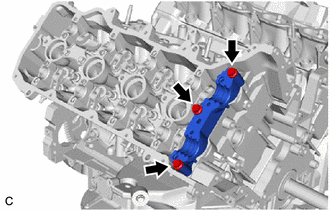
Remove the 3 bolts and camshaft housing LH.
-
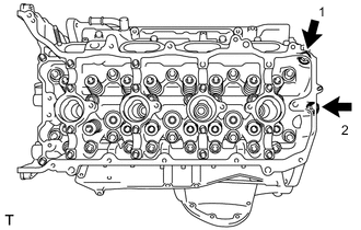
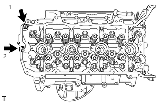
Uniformly loosen and remove the 2 cylinder head set bolts in the order shown in the illustration.
-
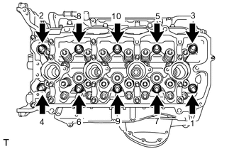
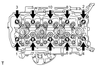
Using a 10 mm bi-hexagon wrench, uniformly loosen the 10 cylinder head set bolts in the order shown in the illustration. Remove the 10 cylinder head set bolts and plate washers.
Note
-
Be careful not to drop the plate washers into the cylinder head LH.
-
Warpage or cracking of the cylinder head LH could result from removing the bolts in an incorrect order.
Tech Tips
Arrange the removed parts in such a way that they can be installed to their original locations.
-
-
Remove the cylinder head LH.
-
-
REMOVE NO. 2 CYLINDER HEAD GASKET
-
Remove the No. 2 cylinder head gasket.
-
-
REMOVE CYLINDER HEAD SUB-ASSEMBLY
-
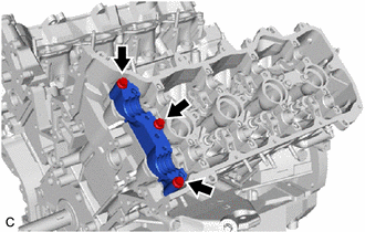
Remove the 3 bolts and camshaft housing RH.
-
Uniformly loosen and remove the 2 cylinder head set bolts in the order shown in the illustration.
-
Using a 10 mm bi-hexagon wrench, uniformly loosen the 10 cylinder head set bolts in the order shown in the illustration. Remove the 10 cylinder head set bolts and plate washers.
Note
-
Be careful not to drop the plate washers into the cylinder head sub-assembly.
-
Warpage or cracking of the cylinder head sub-assembly could result from removing the bolts in an incorrect order.
Tech Tips
Arrange the removed parts in such a way that they can be installed to their original locations.
-
-
Remove the cylinder head sub-assembly.
-
-
REMOVE CYLINDER HEAD GASKET
-
Remove the cylinder head gasket.
-