KNOCK SENSOR REMOVAL
CAUTION / NOTICE / HINT
The necessary procedures (adjustment, calibration, initialization, or registration) that must be performed after parts are removed, installed, or replaced during the knock control sensor removal/installation are shown below.
| Replacement Part | Necessary Procedure | Effect/Inoperative Function when Necessary Procedures are not Performed | Link |
|---|---|---|---|
| Knock control sensor | Inspection after repair |
|
|
PROCEDURE
-
REMOVE INTAKE AIR SURGE TANK ASSEMBLY
-
REMOVE NO. 1 ENGINE COVER SUB-ASSEMBLY
-
REMOVE NO. 2 ENGINE COVER SUB-ASSEMBLY LH
-
REMOVE NO. 4 FUEL PIPE SUB-ASSEMBLY
-
REMOVE CASE SEPARATOR
-

Disconnect the fuel pressure sensor connector.
-
Remove the 4 bolts and case separator.
-
-
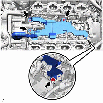
REMOVE KNOCK CONTROL SENSOR
-

*A for Bank 2 Sensor 1 *B for Bank 2 Sensor 2 *C for Bank 1 Sensor 1 *D for Bank 1 Sensor 2 
Engine Front Disconnect the 4 knock control sensor connectors.
-
Remove the 4 bolts and 4 knock control sensors from the cylinder block sub-assembly.
Note
If a knock control sensor has been struck or dropped, replace it.
-