CAMSHAFT POSITION SENSOR REMOVAL
PROCEDURE
-
REMOVE V-BANK COVER SUB-ASSEMBLY
-
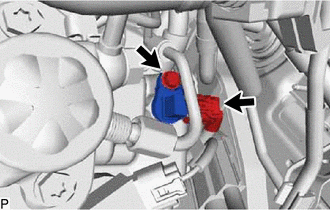
REMOVE CAMSHAFT POSITION SENSOR
-
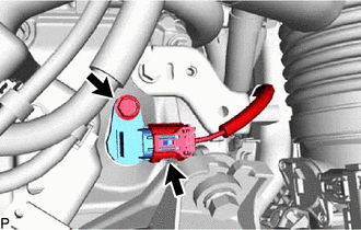
Disconnect the camshaft position sensor connector.
-
Remove the bolt and camshaft position sensor from the cylinder head cover sub-assembly.
Note
If the camshaft position sensor has been struck or dropped, replace it.
-
-
REMOVE VVT SENSOR (for Exhaust Side of Bank 1)
-
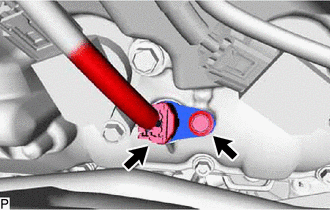
Disconnect the VVT sensor connector.
-
Remove the bolt and VVT sensor from the cylinder head cover sub-assembly LH.
Note
If the VVT sensor has been struck or dropped, replace it.
-
-
REMOVE VVT SENSOR (for Exhaust Side of Bank 2)
-
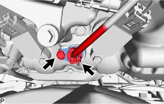
Disconnect the VVT sensor connector.
-
Remove the bolt and VVT sensor from the cylinder head cover sub-assembly.
Note
If the VVT sensor has been struck or dropped, replace it.
-
-
REMOVE VVT SENSOR (for Intake Side of Bank 2)
-
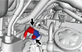
Disconnect the VVT sensor connector.
-
Remove the bolt and VVT sensor from the cylinder head cover sub-assembly.
Note
If the VVT sensor has been struck or dropped, replace it.
-
-
REMOVE NO. 3 FUEL PIPE SUB-ASSEMBLY
-
REMOVE VVT SENSOR (for Intake Side of Bank 1)
-
Disconnect the VVT sensor connector.
-
Remove the bolt and VVT sensor from the cylinder head cover sub-assembly LH.
Note
If the VVT sensor has been struck or dropped, replace it.
-