MASS AIR FLOW METER REMOVAL
CAUTION / NOTICE / HINT
The necessary procedures (adjustment, calibration, initialization, or registration) that must be performed after parts are removed, installed, or replaced during the mass air flow meter sub-assembly removal/installation are shown below.
| Replacement Part | Necessary Procedure | Effect/Inoperative Function when Necessary Procedures are not Performed | Link |
|---|---|---|---|
| Mass air flow meter sub-assembly | Inspection after repair |
|
|
PROCEDURE
-
REMOVE V-BANK COVER SUB-ASSEMBLY
-
REMOVE RADIATOR SUPPORT TO FRAME SEAL RH
-
REMOVE RADIATOR SUPPORT TO FRAME SEAL LH
-
REMOVE LOWER RADIATOR AIR DEFLECTOR
-
REMOVE RADIATOR SUPPORT TO CROSS MEMBER BRACE SUB-ASSEMBLY RH
-
REMOVE AIR CLEANER WITH ELEMENT ASSEMBLY RH
-
REMOVE MASS AIR FLOW METER SUB-ASSEMBLY
-
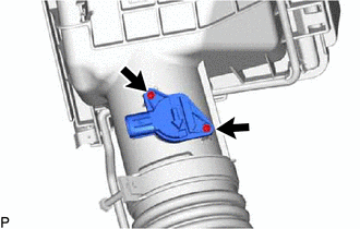
for Bank 2:
-
Remove the 2 screws and mass air flow meter sub-assembly.
Note
If the mass air flow meter sub-assembly has been struck or dropped, replace it.
-
-
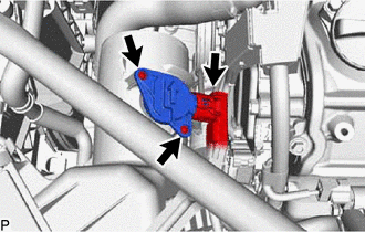
for Bank 1:
-
Disconnect the mass air flow meter sub-assembly connector.
-
Remove the 2 screws and mass air flow meter sub-assembly.
Note
If the mass air flow meter sub-assembly has been struck or dropped, replace it.
-
-