ELECTRICAL KEY OSCILLATOR(for Front) INSTALLATION
CAUTION / NOTICE / HINT
Tech Tips
-
Use the same procedure as for the RHD and LHD vehicles.
-
The procedure listed below is for the LHD vehicles.
-
A bolt without a torque specification is shown in the standard bolt chart.
PROCEDURE
-
INSTALL NO. 1 INDOOR ELECTRICAL KEY ANTENNA ASSEMBLY
-
Move the front seat (RH side) to the rearmost position.
-
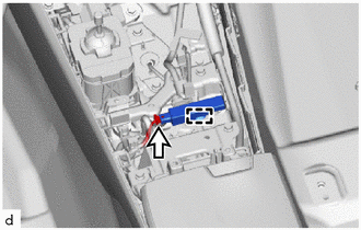
Attach the clamp to install the No. 1 indoor electorical key antenna assembly.
Note
Do not reuse dropped or damaged parts.
-
Connect the connector.
-
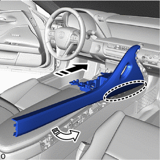

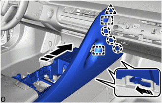
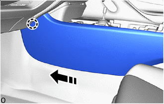
Place Hands Here 
Install in this Direction (1) 
Install in this Direction (2) Move the console upper panel sub-assembly to the installation position diagonally at a slightly slanted angle from the rear upper of the vehicle.
Note
Hold the areas shown in the illustration , lift the console upper panel sub-assembly and while inserting a portion of the claw into the mating hole move it to the installation position.
-
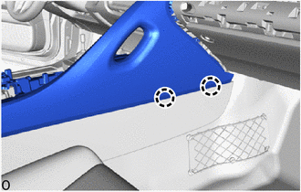
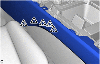
Attach the claws.
-
Attach the claws.
-
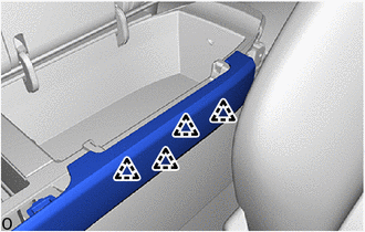
Install in this Direction Slide toward the front of the vehicle to insert the guides and attach the clip and claws.
-
Fold the front seatback (RH side) forward and attach the clips and claws.
-
Return the front seatback (RH side)to the original position and install the bolt.
-

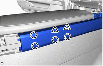
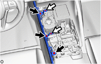
Bolt 
Screw Install the upper console panel sub-assembly with the 2 bolts and 2 screws.
-
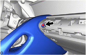
Install in this Direction Slide toward the box panel sub-assembly front of the vehicle and attach the claw.
-
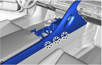
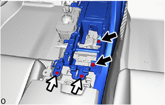
Attach the clips.
-
Attach the clips.
-
Bolt Screw Install the console box panel with the 3 bolts and 2 screws.
-
-
INSTALL UPPER CONSOLE BOX
-
INSTALL NO. 1 GLOVE COMPARTMENT PANEL
-
INSTALL SHIFTING HOLE COVER ASSEMBLY
-
INSTALL SHIFT LEVER KNOB SUB-ASSEMBLY
-
INSTALL RADIO REMOTE TUNING SWITCH ASSEMBLY
-
INSTALL REAR CONSOLE BOX POCKET