ENTRY AND START SYSTEM(for Start Function), Diagnostic DTC:B2274
| DTC Code | DTC Name |
|---|---|
| B2274 | ACC Monitor Malfunction |
DESCRIPTION
This DTC is stored when a malfunction in the ACC output circuit is detected. The ACC output circuit is the circuit between terminal ACCD of the certification ECU (smart key ECU assembly) and the ACC relay.
| DTC No. | Detection Item | DTC Detection Condition | Trouble Area | Note |
|---|---|---|---|---|
| B2274 | ACC Monitor Malfunction | The ACC relay circuit of the certification ECU (smart key ECU assembly) is malfunctioning. (1-trip detection logic*) Tech Tips When the voltage at terminal ACCD is not at the standard, the system is determined to be malfunctioning. |
|
DTC Output Confirmation Operation: |
-
*: Only detected while a malfunction is present.
| Vehicle Condition when Malfunction Detected | Fail-safe Function when Malfunction Detected |
|---|---|
Tech Tips The engine switch can be turned on (IG) and the engine can be started. |
- |
| DTC No. | Data List and Active Test |
|---|---|
| B2274 |
Power Source Control |
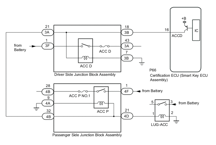
WIRING DIAGRAM
Figure 1. for LHD:
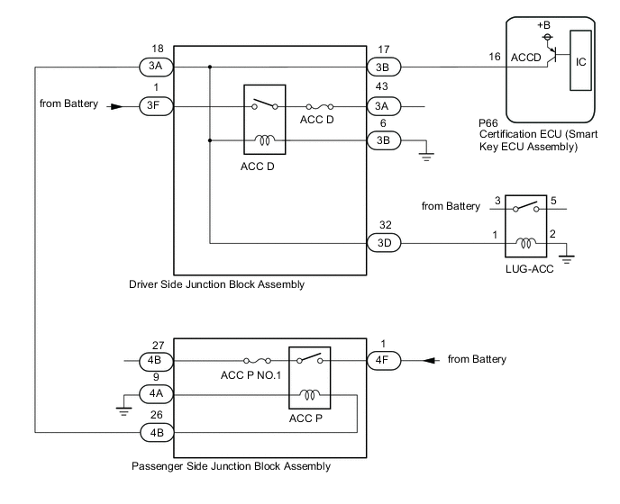
Figure 2. for RHD:
CAUTION / NOTICE / HINT
Note
-
When using the GTS with the engine switch off, connect the GTS to the DLC3 and turn a courtesy light switch on and off at intervals of 1.5 seconds or less until communication between the GTS and the vehicle begins. Then select Model Code "KEY REGIST" under manual mode and enter the following menus: Body Electrical / Entry&Start. While using the GTS, periodically turn a courtesy light switch on and off at intervals of 1.5 seconds or less to maintain communication between the GTS and the vehicle.
-
The entry and start system (for Start Function) uses the LIN communication system and CAN communication system. Inspect the communication function by following How to Proceed with Troubleshooting. Troubleshoot the entry and start system (for Start Function) after confirming that the communication systems are functioning properly.
-
Inspect the fuses of circuits related to this system before performing the following procedure.
-
Before replacing the certification ECU (smart key ECU assembly), refer to the Service Bulletin.
-
After repair, confirm that no DTCs are output by performing "DTC Output Confirmation Operation".
PROCEDURE
-
CHECK VEHICLE CONDITION
-
Check vehicle condition.
Result Proceed to for LHD for RHD
for RHD 
CHECK HARNESS AND CONNECTOR (DRIVER SIDE JUNCTION BLOCK ASSEMBLY - CERTIFICATION ECU (SMART KEY ECU ASSEMBLY), POWER SUPPLY AND BODY GROUND) Click here
for LHD 
-
-
CHECK HARNESS AND CONNECTOR (DRIVER SIDE JUNCTION BLOCK ASSEMBLY - CERTIFICATION ECU (SMART KEY ECU ASSEMBLY), POWER SUPPLY AND BODY GROUND)
-
Disconnect the 3B and 3F driver side junction block assembly connectors.
-
Disconnect the P66 certification ECU (smart key ECU assembly) connector.
-
Measure the resistance according to the value(s) in the table below.
Standard Resistance Tester Connection Condition Specified Condition P66-16 (ACCD) - 3B-17 Always Below 1 Ω 3B-6 - Body ground Always Below 1 Ω P66-16 (ACCD) or 3B-17 - Other terminals and body ground Always 10 kΩ or higher -
Measure the voltage according to the value(s) in the table below.
Standard Voltage Tester Connection Condition Specified Condition 3F-1 - Body ground Always 11 to 14 V Result Proceed to OK NG
NG 
REPAIR OR REPLACE HARNESS OR CONNECTOR
OK
-
-
CHECK CERTIFICATION ECU (SMART KEY ECU ASSEMBLY)
-
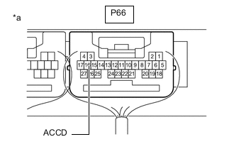
*a Component with harness connected
(Certification ECU (Smart Key ECU Assembly))
Reconnect the certification ECU (smart key ECU assembly) connector.
-
Measure the voltage according to the value(s) in the table below.
Standard Voltage Tester Connection Switch Condition Specified Condition P66-16 (ACCD) - Body ground Engine switch off → Engine switch on (ACC) 1 V or less → 8.5 V or higher Result Proceed to OK NG
NG
REPLACE CERTIFICATION ECU (SMART KEY ECU ASSEMBLY)
OK
-
-
CHECK HARNESS AND CONNECTOR (LUG-ACC RELAY - DRIVER SIDE JUNCTION BLOCK ASSEMBLY, POWER SUPPLY AND BODY GROUND)
-
Disconnect the 3D driver side junction block assembly connector.
-
Remove the LUG-ACC relay.
-
Measure the resistance according to the value(s) in the table below.
Standard Resistance Tester Connection Condition Specified Condition 3D-32 - LUG-ACC relay installation terminal 1 Always Below 1 Ω LUG-ACC relay installation terminal 2 - Body ground Always Below 1 Ω 3D-32 or LUG-ACC relay installation terminal 1 - Other terminals and body ground Always 10 kΩ or higher -
Measure the voltage according to the value(s) in the table below.
Standard Voltage Tester Connection Condition Specified Condition LUG-ACC relay installation terminal 3 - Body ground Always 11 to 14 V Result Proceed to OK NG
NG
REPAIR OR REPLACE HARNESS OR CONNECTOR
OK
-
-
CHECK HARNESS AND CONNECTOR (PASSENGER SIDE JUNCTION BLOCK ASSEMBLY - DRIVER SIDE JUNCTION BLOCK ASSEMBLY, POWER SUPPLY AND BODY GROUND)
-
Disconnect the 4B, 4A and 4F passenger side junction block assembly connectors.
-
Disconnect the 3A driver side junction block assembly connector.
-
Measure the resistance according to the value(s) in the table below.
Standard Resistance Tester Connection Condition Specified Condition 3A-18 - 4B-26 Always Below 1 Ω 4A-9 - Body ground Always Below 1 Ω 3A-18 or 4B-26 - Other terminals and body ground Always 10 kΩ or higher -
Measure the voltage according to the value(s) in the table below.
Standard Voltage Tester Connection Condition Specified Condition 4F-1 - Body ground Always 11 to 14 V -
Reconnect the 3A driver side junction block assembly connector.
Result Proceed to OK NG
NG
REPAIR OR REPLACE HARNESS OR CONNECTOR
OK
-
-
CHECK DRIVER SIDE JUNCTION BLOCK ASSEMBLY (ACC D RELAY)
-
Remove the driver side junction block assembly.
-
Reconnect the all driver side junction block assembly connectors.
-
Measure the voltage according to the value(s) in the table below.
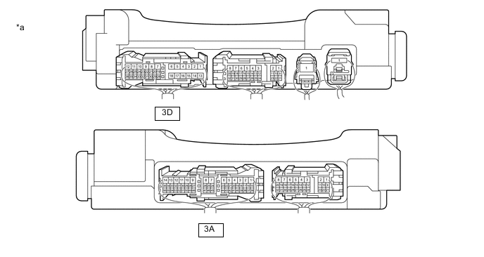
*a Component with harness connected
(Driver Side Junction Block Assembly)
- - Standard Voltage Tester Connection Switch Condition Specified Condition 3A-43 - Body ground Engine switch on (ACC) 11 to 14 V 3A-18 - Body ground Engine switch on (ACC) 8.5 to 14 V 3D-32 - Body ground Engine switch on (ACC) 8.5 to 14 V Result Proceed to OK NG
NG
REPLACE DRIVER SIDE JUNCTION BLOCK ASSEMBLY Click here
OK
-
-
CHECK PASSENGER SIDE JUNCTION BLOCK ASSEMBLY (ACC P RELAY)
-
Remove the passenger side junction block assembly.
-
Reconnect the all passenger side junction block assembly connectors.
-
Measure the voltage according to the value(s) in the table below.
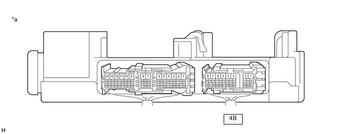
*a Component with harness connected
(Passenger Side Junction Block Assembly)
- - Standard Voltage Tester Connection Switch Condition Specified Condition 4B-27 - Body ground Engine switch on (ACC) 11 to 14 V Result Proceed to OK NG
NG
REPLACE PASSENGER SIDE JUNCTION BLOCK ASSEMBLY Click here
OK
-
-
INSPECT LUG-ACC RELAY
-
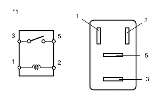
*1 LUG-ACC Relay Measure the resistance according to the value(s) in the table below.
Standard Resistance Tester Connection Condition Specified Condition 3 - 5 Battery voltage applied between terminals 1 and 2 Below 1 Ω Battery voltage not applied between terminals 1 and 2 10 kΩ or higher Result Proceed to OK NG
OK
END (TEMPORARY CONNECTION FAILURE IS SUSPECTED) Click here
NG
REPLACE LUG-ACC RELAY
-
-
CHECK HARNESS AND CONNECTOR (DRIVER SIDE JUNCTION BLOCK ASSEMBLY - CERTIFICATION ECU (SMART KEY ECU ASSEMBLY), POWER SUPPLY AND BODY GROUND)
-
Disconnect the 3B and 3F driver side junction block assembly connectors.
-
Disconnect the P66 certification ECU (smart key ECU assembly) connector.
-
Measure the resistance according to the value(s) in the table below.
Standard Resistance Tester Connection Condition Specified Condition P66-16 (ACCD) - 3B-18 Always Below 1 Ω 3B-7 - Body ground Always Below 1 Ω P66-16 (ACCD) or 3B-18 - Other terminals and body ground Always 10 kΩ or higher -
Measure the voltage according to the value(s) in the table below.
Standard Voltage Tester Connection Condition Specified Condition 3F-1 - Body ground Always 11 to 14 V Result Proceed to OK NG
NG
REPAIR OR REPLACE HARNESS OR CONNECTOR
OK
-
-
CHECK CERTIFICATION ECU (SMART KEY ECU ASSEMBLY)
-
*a Component with harness connected
(Certification ECU (Smart Key ECU Assembly))
Reconnect the certification ECU (smart key ECU assembly) connector.
-
Measure the voltage according to the value(s) in the table below.
Standard Voltage Tester Connection Switch Condition Specified Condition P66-16 (ACCD) - Body ground Engine switch off → Engine switch on (ACC) 1 V or less → 8.5 V or higher Result Proceed to OK NG
NG
REPLACE CERTIFICATION ECU (SMART KEY ECU ASSEMBLY)
OK
-
-
CHECK HARNESS AND CONNECTOR (PASSENGER SIDE JUNCTION BLOCK ASSEMBLY - DRIVER SIDE JUNCTION BLOCK ASSEMBLY, POWER SUPPLY AND BODY GROUND)
-
Disconnect the 4B, 4A and 4F passenger side junction block assembly connectors.
-
Disconnect the 3A driver side junction block assembly connector.
-
Measure the resistance according to the value(s) in the table below.
Standard Resistance Tester Connection Condition Specified Condition 3A-21 - 4B-32 Always Below 1 Ω 4A-9 - Body ground Always Below 1 Ω 3A-21 or 4B-32 - Other terminals and body ground Always 10 kΩ or higher -
Measure the voltage according to the value(s) in the table below.
Standard Voltage Tester Connection Condition Specified Condition 4F-1 - Body ground Always 11 to 14 V -
Reconnect the 3A driver side junction block assembly connector.
Result Proceed to OK NG
NG
REPAIR OR REPLACE HARNESS OR CONNECTOR
OK
-
-
CHECK HARNESS AND CONNECTOR (LUG-ACC RELAY - PASSENGER SIDE JUNCTION BLOCK ASSEMBLY, POWER SUPPLY AND BODY GROUND)
-
Disconnect the 4D passenger side junction block assembly connector.
-
Remove the LUG-ACC relay.
-
Measure the resistance according to the value(s) in the table below.
Standard Resistance Tester Connection Condition Specified Condition 4D-21 - LUG-ACC relay installation terminal 1 Always Below 1 Ω LUG-ACC relay installation terminal 2 - Body ground Always Below 1 Ω 4D-21 or LUG-ACC relay installation terminal 1 - Other terminals and body ground Always 10 kΩ or higher -
Measure the voltage according to the value(s) in the table below.
Standard Voltage Tester Connection Condition Specified Condition LUG-ACC relay installation terminal 3 - Body ground Always 11 to 14 V Result Proceed to OK NG
NG
REPAIR OR REPLACE HARNESS OR CONNECTOR
OK
-
-
CHECK DRIVER SIDE JUNCTION BLOCK ASSEMBLY (ACC D RELAY)
-
Remove the driver side junction block assembly.
-
Reconnect the all driver side junction block assembly connectors.
-
Measure the voltage according to the value(s) in the table below.
*a Component with harness connected
(Driver Side Junction Block Assembly)
- - Standard Voltage Tester Connection Switch Condition Specified Condition 3A-43 - Body ground Engine switch on (ACC) 11 to 14 V 3A-21 - Body ground Engine switch on (ACC) 8.5 to 14 V Result Proceed to OK NG
NG
REPLACE DRIVER SIDE JUNCTION BLOCK ASSEMBLY Click here
OK
-
-
CHECK PASSENGER SIDE JUNCTION BLOCK ASSEMBLY (ACC P RELAY)
-
Remove the passenger side junction block assembly.
-
Reconnect the all passenger side junction block assembly connectors.
-
Measure the voltage according to the value(s) in the table below.
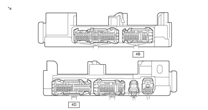
*a Component with harness connected
(Passenger Side Junction Block Assembly)
- - Standard Voltage Tester Connection Switch Condition Specified Condition 4B-28 - Body ground Engine switch on (ACC) 11 to 14 V 4D-21 - Body ground Engine switch on (ACC) 8.5 to 14 V Result Proceed to OK NG
NG
REPLACE PASSENGER SIDE JUNCTION BLOCK ASSEMBLY Click here
OK
-
-
INSPECT LUG-ACC RELAY
-
*1 LUG-ACC Relay Measure the resistance according to the value(s) in the table below.
Standard Resistance Tester Connection Condition Specified Condition 3 - 5 Battery voltage applied between terminals 1 and 2 Below 1 Ω Battery voltage not applied between terminals 1 and 2 10 kΩ or higher Result Proceed to OK NG
OK
END (TEMPORARY CONNECTION FAILURE IS SUSPECTED) Click here
NG
REPLACE LUG-ACC RELAY
-