POWER DOOR LOCK CONTROL SYSTEM Door Lock Indicator does not Operate Properly
DESCRIPTION
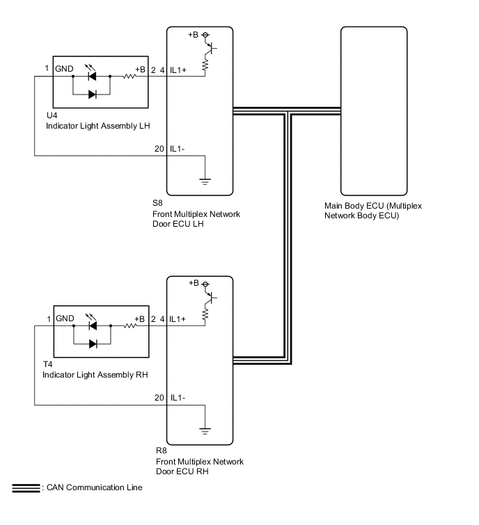
The front multiplex network door ECU receives signals from the main body ECU (multiplex network body ECU) via CAN communication system. The front multiplex network door ECU operates the indicator light assembly according to these signals.
WIRING DIAGRAM
CAUTION / NOTICE / HINT
Note
-
The power door lock control system uses the CAN communication system. Inspect the communication function by following How to Proceed with Troubleshooting. Troubleshoot the power door lock control system after confirming that the communication systems are functioning properly.
-
If the main body ECU (multiplex network body ECU) is replaced, refer to the Service Bulletin.
PROCEDURE
-
CHECK WIRELESS DOOR LOCK CONTROL SYSTEM OPERATION
-
Check that the wireless door lock control system operates normally via electrical key transmitter sub-assembly.
OK Wireless door lock operates normally. Result Proceed to OK NG
NG 
GO TO WIRELESS DOOR LOCK CONTROL SYSTEM Click here
OK 
-
-
CHECK PROBLEM SYMPTOM
-
Check the problem symptom.
Tech Tips
Check the customize settings of "Door Lock Indicator Light Out Adjust (FL)" and "Door Lock Indicator Light Out Adjust (FR)".
Result Result Proceed to Indicator light assembly LH does not operate properly A Indicator light assembly RH does not operate properly B Turn off control function does not operate properly C
B 
INSPECT INDICATOR LIGHT ASSEMBLY RH Click here
C
REPLACE MAIN BODY ECU (MULTIPLEX NETWORK BODY ECU) Click here
A
-
-
INSPECT INDICATOR LIGHT ASSEMBLY LH
-
Remove the indicator light assembly LH.
-
Inspect the indicator light assembly LH.
Result Proceed to OK NG
NG
REPLACE INDICATOR LIGHT ASSEMBLY LH Click here
OK
-
-
CHECK HARNESS AND CONNECTOR (FRONT MULTIPLEX NETWORK DOOR ECU LH - INDICATOR LIGHT ASSEMBLY LH)
-
Disconnect the S8 front multiplex network door ECU LH connector.
-
Disconnect the U4 indicator light assembly LH connector.
-
Measure the resistance according to the value(s) in the table below.
Standard Resistance Tester Connection Condition Specified Condition S8-4 (IL1+) - U4-2 (+B) Always Below 1 Ω S8-20 (IL1-) - U4-1 (GND) Always Below 1 Ω S8-4 (IL1+) or U4-2 (+B) - Other terminals and body ground Always 10 kΩ or higher S8-20 (IL1-) or U4-1 (GND) - Other terminals and body ground Always 10 kΩ or higher Result Proceed to OK NG
OK
REPLACE FRONT MULTIPLEX NETWORK DOOR ECU LH Click here
NG
REPAIR OR REPLACE HARNESS OR CONNECTOR
-
-
INSPECT INDICATOR LIGHT ASSEMBLY RH
-
Remove the indicator light assembly RH.
-
Inspect the indicator light assembly RH.
Result Proceed to OK NG
NG
REPLACE INDICATOR LIGHT ASSEMBLY RH Click here
OK
-
-
CHECK HARNESS AND CONNECTOR (FRONT MULTIPLEX NETWORK DOOR ECU RH - INDICATOR LIGHT ASSEMBLY RH)
-
Disconnect the R8 front multiplex network door ECU RH connector.
-
Disconnect the T4 indicator light assembly RH connector.
-
Measure the resistance according to the value(s) in the table below.
Standard Resistance Tester Connection Condition Specified Condition R8-4 (IL1+) - T4-2 (+B) Always Below 1 Ω R8-20 (IL1-) - T4-1 (GND) Always Below 1 Ω R8-4 (IL1+) or T4-2 (+B) - Other terminals and body ground Always 10 kΩ or higher R8-20 (IL1-) or T4-1 (GND) - Other terminals and body ground Always 10 kΩ or higher Result Proceed to OK NG
OK
REPLACE FRONT MULTIPLEX NETWORK DOOR ECU RH Click here
NG
REPAIR OR REPLACE HARNESS OR CONNECTOR
-