POWER DOOR LOCK CONTROL SYSTEM TERMINALS OF ECU
-
CHECK DRIVER SIDE JUNCTION BLOCK ASSEMBLY AND MAIN BODY ECU (MULTIPLEX NETWORK BODY ECU)
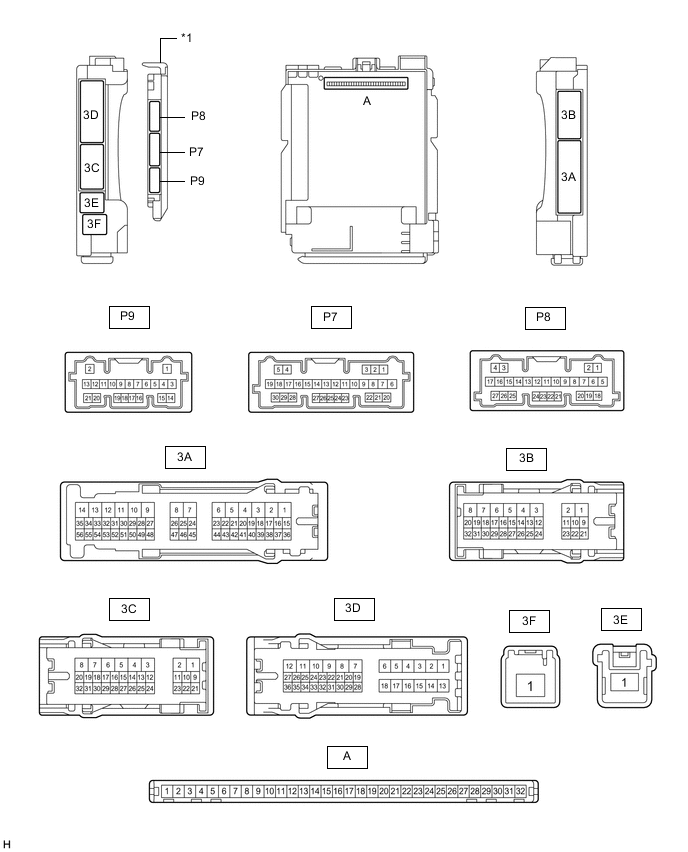
*1 Main Body ECU (Multiplex Network Body ECU) - -
-
Remove the main body ECU (multiplex network body ECU) from the driver side junction block assembly.
-
Reconnect the driver side junction block assembly connectors.
-
Measure the voltage and resistance according to the value(s) in the table below.
Tester Connection Wiring Color Input/Output Terminal Description Condition Specified Condition Related Data List Item A-11 (GND1) - Body ground - - Ground Always Below 1 Ω - A-30 (ACC) - Body ground - Input ACC power supply Engine switch on (ACC) 11 to 14 V ACC SW Engine switch off Below 1 V A-31 (BECU) - Body ground - Input Battery power supply Always 11 to 14 V - A-32 (IG) - Body ground - Input IG power supply Engine switch on (IG) 11 to 14 V IG SW Engine switch off Below 1 V -
Install the main body ECU (multiplex network body ECU) to the driver side junction block assembly.
-
Measure the voltage and check for pulses according to the value(s) in the table below.
Tester Connection Wiring Color Input/Output Terminal Description Condition Specified Condition Related Data List Item P7-1 (FLCY) - Body ground R - Body ground Input Courtesy light switch LH input Front door LH open → closed Below 1 V → 4.7 to 5.3 V FL Door Courtesy SW P7-6 (FRCY) - Body ground SB - Body ground Input Courtesy light switch RH input Front door RH open → closed Below 1 V → 4.7 to 5.3 V FR Door Courtesy SW P9-18 (L2) - Body ground Y - Body ground Input Driver and front passenger door key-linked lock input Driver or front passenger door key cylinder turned to neutral position → on (lock) Pulse generation → Below 1 V Door Key SW-Lock P9-19 (UL2) - Body ground BR - Body ground Input Front passenger door key-linked unlock input Front passenger door key cylinder turned to neutral position → on (unlock) Pulse generation → Below 1 V Door Key SW-Unlock P9-17 (UL3) - Body ground LG - Body ground Input Driver door key-linked unlock input Driver door key cylinder turned to neutral position → on (unlock) Pulse generation → Below 1 V D Door Key SW-UL 3D-18 (ACT+) - Body ground LA-G - Body ground Output Door lock motor lock drive output Door control switch or door key cylinder off → on (lock) Below 1 V → 11 to 14 V → Below 1 V - 3A-2 (ACT+) - Body ground G - Body ground Output Door lock motor lock drive output Door control switch or door key cylinder off → on (lock) Below 1 V → 11 to 14 V → Below 1 V - 3A-1 (ACT-) - Body ground LG - Body ground Output Front passenger door lock motor unlock drive output Door control switch front passenger door key cylinder off → on (unlock) Below 1 V → 11 to 14 V → Below 1 V - 3D-8 (ACTD) - Body ground LA-LG - Body ground Output Driver door lock motor unlock drive output Door control switch or driver door key cylinder off → on (unlock) Below 1 V → 11 to 14 V → Below 1 V - 3B-14 (LSFR) - Body ground*1
3D-31 (LSFR) - Body ground*2
GR - Body ground*1
P - Body ground*2
Input Front door RH unlock detection switch input Front door RH locked → unlocked Pulse generation → Below 1 V FR Door Lock Pos 3D-31 (LSFL) - Body ground*1
3A-15 (LSFL) - Body ground*2
P - Body ground*1
Y - Body ground*2
Input Front door LH unlock detection switch input Front door LH locked → unlocked Pulse generation → Below 1 V FL Door Lock Pos 3B-13 (L1) - Body ground*1
3A-38 (L1) - Body ground*2
P - Body ground Input Front passenger door control switch input Front passenger door control switch off → on (lock) Pulse generation → Below 1 V Door Lock Switch Status 3B-12 (UL1) - Body ground*1
3A-39 (UL1) - Body ground*2
R - Body ground Input Front passenger door control switch input Front passenger door control switch off → on (unlock) Pulse generation → Below 1 V Door Unlock Switch Status 3A-46 (GSW) - Body ground Y - Body ground Input Collision detection input Engine switch on (IG) 2.9 to 4.2 V -
-
*1: for LHD
-
*2: for RHD
-
-
-
CHECK DOUBLE LOCK DOOR CONTROL RELAY ASSEMBLY (w/ Double Locking System)

-
Disconnect the P83 double lock door control relay assembly connector.
-
Measure the voltage and resistance according to the value(s) in the table below.
Tester Connection Wiring Color Input/Output Terminal Description Condition Specified Condition Related Data List Item P83-12 (+B) - Body ground LA-B - Body ground Input Battery power supply Always 11 to 14 V - P83-11 (CPUB) - Body ground LA-W - Body ground Input Battery power supply Always 11 to 14 V - P83-7 (GND) - Body ground W-B - Body ground - Ground Always Below 1 Ω - -
Reconnect the P83 double lock door control relay assembly connector.
-
Measure the voltage and check for pulses according to the value(s) in the table below.
Tester Connection Wiring Color Input/Output Terminal Description Condition Specified Condition Related Data List Item P83-8 (ACTS) - Body ground LA-G - Body ground Output All door double lock motor set on output Double lock unset → set Below 1 V → 11 to 14 V - P83-1 (ACTR) - Body ground LA-SB - Body ground Output All door double lock motor set off output Double lock set → unset Below 1 V → 11 to 14 V - P83-6 (DLPD) - Body ground LA-P - Body ground*1
LA-V - Body ground*2
Input Driver door double lock position switch input Double lock unset → set Pulse generation → Below 1 V - P83-5 (DLPP) - Body ground LA-V - Body ground*1
LA-P - Body ground*2
Input Front passenger door double lock position switch input Double lock unset → set Pulse generation → Below 1 V -
-
*1: for LHD
-
*2: for RHD
-
-
-
CHECK AIRBAG ECU ASSEMBLY