NETWORK GATEWAY ECU INSTALLATION
CAUTION / NOTICE / HINT
Tech Tips
-
Use the same procedure for RHD and LHD vehicles.
-
The procedure listed below is for LHD vehicles.
PROCEDURE
-
INSTALL NETWORK GATEWAY ECU
-
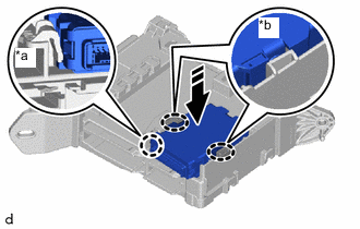
*a Check that the network gateway ECU is securely engaged with the protrusion of the passenger side junction block assembly *b Check that the network gateway ECU is securely installed 
Push Area 
Install in this Direction Attach the claw to install the network gateway ECU connector.
Note
Do not use a network gateway ECU that has been dropped or subjected to a strong shock.
-
-
INSTALL PASSENGER SIDE JUNCTION BLOCK ASSEMBLY WITH NETWORK GATEWAY ECU
-
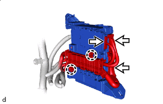

Connector Attach the claw to connect the instrument panel wire and install the passenger side junction block assembly with network gateway ECU.
-
Connect the 3 connectors.
-
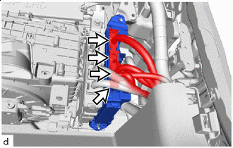
Connector Connect the 4 connectors to connect the passenger side junction block assembly with network gateway ECU.
-
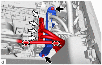

Nut Connector Install the passenger side junction block assembly with network gateway ECU with the 2 nuts.
- Torque:
- 8.0 N*m { 82 kgf*cm, 71 in.*lbf }
-
Connect the 4 connectors.
-
Attach the clamp and connect the wire harness.
-
-
INSTALL FRONT STEERING CONTROL ECU
-
INSTALL GLOVE COMPARTMENT DOOR ASSEMBLY
-
INSTALL NO. 2 INSTRUMENT PANEL GARNISH SUB-ASSEMBLY
-
INSTALL LOWER NO. 2 INSTRUMENT PANEL AIRBAG ASSEMBLY
-
CONNECT CABLE TO NEGATIVE BATTERY TERMINAL
Note
When disconnecting the cable, some systems need to be initialized after the cable is reconnected.
-
INSTALL NO. 2 DECK BOARD
-
PERFORM DIAGNOSTIC SYSTEM CHECK
-
CHECK SRS WARNING LIGHT