NETWORK GATEWAY ECU REMOVAL
CAUTION / NOTICE / HINT
The necessary procedures (adjustment, calibration, initialization, or registration) that must be performed after parts are removed, installed, or replaced during the network gateway ECU removal/installation are shown below.
| Replacement part or procedure | Necessary procedures | Effects/Inoperative when not performed | Link |
|---|---|---|---|
| Disconnect cable from negative (-) battery terminal | Memorize steering angle neutral point | LKA/LDA system | |
| Pre-collision system | |||
| Parking assist monitor system | |||
| Steering sensor zero point calibration | Variable gear ratio steering system |
Tech Tips
-
Use the same procedure for RHD and LHD vehicles.
-
The procedure listed below is for LHD vehicles.
PROCEDURE
-
PRECAUTION
CAUTION:
Some of these service operations affect the SRS airbag system. Read the precautionary notices concerning the SRS airbag system before servicing.
Note
-
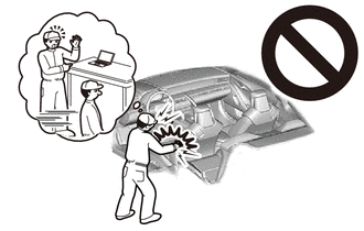
When disassembling the network gateway ECU, eliminate static electricity by touching the vehicle body to prevent the components from being damaged.
-
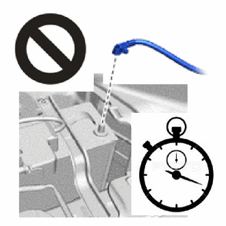
After turning the engine switch off, waiting time may be required before disconnecting the cable from the negative (-) battery terminal. Therefore, make sure to read the disconnecting the cable from the negative (-) battery terminal notices before proceeding with work.
-
-
REMOVE NO. 2 DECK BOARD
-
DISCONNECT CABLE FROM NEGATIVE BATTERY TERMINAL
CAUTION:
-
Wait at least 90 seconds after disconnecting the cable from the negative (-) battery terminal to disable the SRS system.
-
If the airbag deploys for any reason, it may cause a serious accident.
Note
When disconnecting the cable, some systems need to be initialized after the cable is reconnected.
-
-
REMOVE LOWER NO. 2 INSTRUMENT PANEL AIRBAG ASSEMBLY
-
REMOVE NO. 2 INSTRUMENT PANEL GARNISH SUB-ASSEMBLY
-
REMOVE GLOVE COMPARTMENT DOOR ASSEMBLY
-
REMOVE FRONT STEERING CONTROL ECU
-
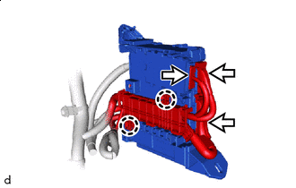
REMOVE PASSENGER SIDE JUNCTION BLOCK ASSEMBLY WITH NETWORK GATEWAY ECU
-
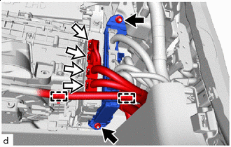

Nut 
Connector Detach the clamp and disconnect the wire harness.
-
Disconnect the 4 connectors.
-
Remove the 2 nuts.
-
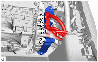
Connector Disconnect the 4 connectors and passenger side junction block assembly with network gateway ECU.
-
Connector Disconnect the 3 connectors.
-
Detach the claw and disconnect the instrument panel wire and remove the passenger side junction block assembly with network gateway ECU.
-
-
REMOVE NETWORK GATEWAY ECU
-
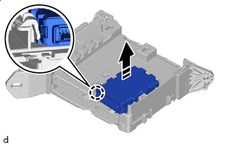

Remove in this Direction Detach the claw and remove the network gateway ECU.
Note
Do not use a network gateway ECU that has been dropped or subjected to a strong shock.
-