CXPI COMMUNICATION SYSTEM TERMINALS OF ECU
Note
-
After turning the engine switch off, waiting time may be required before disconnecting the cable from the negative (-) battery terminal. Therefore, make sure to read the disconnecting the cable from the negative (-) battery terminal notices before proceeding with work.
-
When disconnecting the cable from the negative (-) battery terminal while performing repairs, some systems need to be initialized after the cable is reconnected.
-
CHECK DRIVER SIDE JUNCTION BLOCK ASSEMBLY AND MAIN BODY ECU (MULTIPLEX NETWORK BODY ECU)
-
Remove the main body ECU (multiplex network body ECU).
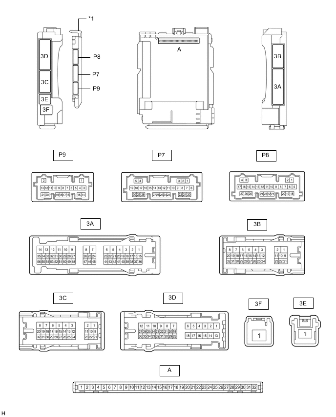
*1 Main Body ECU (Multiplex Network Body ECU) - - -
Connect the driver side junction block assembly.
-
Measure the voltage and resistance according to the value(s) in the table below.
Tester Connection Wiring Color Terminal Description Condition Specified Condition A-11 (GND1) - Body ground None - Body ground Ground Always Below 1 Ω A-31 (BECU) - Body ground None - Body ground Battery power supply Always 11 to 14 V A-30 (ACC) - Body ground None - Body ground ACC power supply Engine switch on (ACC) 11 to 14 V Engine switch off Below 1 V A-32 (IG) - Body ground None - Body ground IG power supply Engine switch on (IG) 11 to 14 V Engine switch off Below 1 V
-
-
NO. 1 SEMICONDUCTOR POWER INTEGRATION ECU

*a Component without harness connected
(No. 1 semiconductor power integration ECU)
- - Terminal No. (Symbol) Wiring Color Terminal Description Condition Specified Condition A79-1 (+B) - Body ground R - Body ground Battery power supply Always 8 to 14 V A80-1 (L) - Body ground G - Body ground No. 1 headlight ECU sub-assembly LH power supply Engine switch off Below 3 V Engine switch on (IG) 8 V or higher A80-2 (HI) - Body ground R - Body ground No. 1 headlight ECU sub-assembly RH power supply Engine switch off Below 3 V Engine switch on (IG) 8 V or higher A80-6 (GND2) - Body ground W-B - Body ground Ground Always Below 1 Ω A80-9 (IG) - Body ground L - Body ground Ignition power supply Engine switch off Below 1.5 V Engine switch on (IG) 8 to 14 V A80-13 (GND1) - Body ground W-B - Body ground Ground Always Below 1 Ω A80-14 (-S) - Body ground R - Body ground No. 1 headlight ECU sub-assembly operation signal input Engine switch off 6 V or higher Engine switch on (IG) Below 1.5 V A80-15 (-S) - Body ground V - Body ground No. 1 headlight ECU sub-assembly operation signal input Engine switch off 6 V or higher Engine switch on (IG) Below 1.5 V
-
Check for pulses according to the value(s) in the table below.
Terminal No. (Symbol) Wiring Color Terminal Description Condition Specified Condition A80-7 (CXPI) - Body ground SB - Body ground CXPI communication line Engine switch on (IG) Pulse generation
-
-
NO. 3 SEMICONDUCTOR POWER INTEGRATION ECU

*a Component without harness connected
(No. 3 semiconductor power integration ECU)
- - Terminal No. (Symbol) Wiring Color Terminal Description Condition Specified Condition b11-1 (+B) - Body ground B - Body ground Battery power supply Always 8 to 14 V X99-1 (OUT) - Body ground W - Body ground Stop lights, high mounted stop light output Brake pedal released Below 3 V Brake pedal depressed 8 V or higher X99-2 (L) - Body ground R - Body ground Window defogger output Engine switch on (IG), window defogger switch off Below 3 V Engine switch on (IG), window defogger switch on 8 V or higher X99-4 (L) - Body ground LA-R - Body ground Back-up output Engine running, shift lever in any position other than R Below 3 V Engine running, shift lever in R 8 V or higher X99-6 (GND2) - Body ground LA - Body ground Ground Always Below 1 Ω X99-9 (IG) - Body ground LA-B - Body ground Ignition power supply Engine switch off Below 1.5 V Engine switch on (IG) 8 to 14 V X99-10 (STP) - Body ground R - Body ground Stop light operation signal input Brake pedal released Below 1.5 V Brake pedal depressed 6 V or higher X99-11 (+S) - Body ground L - Body ground Back-up light operation signal input Engine running, shift lever in any position other than R Below 1.5 V Engine running, shift lever in R 6 V or higher X99-13 (GND1) - Body ground LA - Body ground Ground Always Below 1 Ω X99-14 (ACC) - Body ground BE - Body ground ACC stop lights operation signal input Engine switch off 6 V or higher Engine switch on (IG) Below 1.5 V X99-16 (L) - Body ground LA-P - Body ground Rear taillights output Rear taillights not illuminated Below 3 V Rear taillights illuminated 8 V or higher
-
Check for pulses according to the value(s) in the table below.
Terminal No. (Symbol) Wiring Color Terminal Description Condition Specified Condition X99-7 (CXPI) - Body ground V - Body ground CXPI communication line Engine switch on (IG) Pulse generation
-