LIN COMMUNICATION SYSTEM TERMINALS OF ECU
-
CHECK DRIVER SIDE JUNCTION BLOCK ASSEMBLY AND MAIN BODY ECU (MULTIPLEX NETWORK BODY ECU)
-
Remove the main body ECU (multiplex network body ECU).
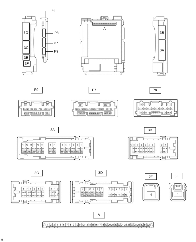
*1 Main Body ECU (Multiplex Network Body ECU) - - -
Measure the voltage and resistance according to the value(s) in the table below.
Tester Connection Wiring Color Terminal Description Condition Specified Condition A-11 (GND1) - Body ground - Ground Always Below 1 Ω A-31 (BECU) - Body ground - Battery power supply Always 11 to 14 V A-30 (ACC) - Body ground - ACC power supply Engine switch on (ACC) 11 to 14 V Engine switch off Below 1 V A-32 (IG) - Body ground - IG power supply Engine switch on (IG) 11 to 14 V Engine switch off Below 1 V -
Install the main body ECU (multiplex network body ECU).
-
Measure the pulse according to the value(s) in the table below.
Tester Connection Wiring Color Terminal Description Condition Specified Condition A-16 (LIN2) - Body ground - LIN communication line Engine switch on (IG) Pulse generation
-
-
CHECK FRONT MULTIPLEX NETWORK DOOR ECU LH

-
Disconnect the S9 front multiplex network door ECU LH connector.
-
Measure the resistance and voltage according to the value(s) in the table below.
Terminal No. (Symbol) Wiring Color Terminal Description Condition Specified Condition S9-3 (SIG) - Body ground LA-B - Body ground IG power supply Engine switch off Below 1 V Engine switch on (IG) 11 to 14 V S9-4 (CPUB) - Body ground LA-LG - Body ground Battery power supply Always 11 to 14 V S9-6 (BDR) - Body ground R - Body ground Battery power supply Always 11 to 14 V S9-16 (BCUT) - Body ground V - Body ground Battery power supply Always 11 to 14 V S9-1 (GND) - Body ground W-B - Body ground Ground Always Below 1 Ω -
Measure the pulse according to the value(s) in the table below.
Terminal No. (Symbol) Wiring Color Terminal Description Condition Specified Condition S9-11 (LIN1) - Body ground SB - Body ground LIN communication line Engine switch on (IG) Pulse generation S9-13 (LIN3) - Body ground W - Body ground LIN communication line Engine switch on (IG) Pulse generation
-
-
CHECK FRONT MULTIPLEX NETWORK DOOR ECU RH

-
Disconnect the R9 front multiplex network door ECU RH connector.
-
Measure the resistance and voltage according to the value(s) in the table below.
Terminal No. (Symbol) Wiring Color Terminal Description Condition Specified Condition R9-3 (SIG) - Body ground LA-B - Body ground IG power supply Engine switch off Below 1 V Engine switch on (IG) 11 to 14 V R9-4 (CPUB) - Body ground LA-LG - Body ground Battery power supply Always 11 to 14 V R9-6 (BDR) - Body ground R - Body ground Battery power supply Always 11 to 14 V R9-1 (GND) - Body ground W-B - Body ground Ground Always Below 1 Ω -
Measure the pulse according to the value(s) in the table below.
Terminal No. (Symbol) Wiring Color Terminal Description Condition Specified Condition R9-11 (LIN1) - Body ground SB - Body ground LIN communication line Engine switch on (IG) Pulse generation R9-13 (LIN3) - Body ground W - Body ground LIN communication line Engine switch on (IG) Pulse generation
-
-
CHECK MULTIPLEX NETWORK MASTER SWITCH ASSEMBLY
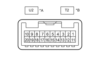
*A for LHD *B for RHD
-
Disconnect the U2*1 or T2*2 multiplex network master switch assembly connector.
-
*1: for LHD
-
*2: for RHD
-
-
Measure the resistance and voltage according to the value(s) in the table below.
for LHD Terminal No. (Symbol) Wiring Color Terminal Description Condition Specified Condition U2-11 (B) - Body ground LA-GR - Body ground Battery power supply Always 11 to 14 V U2-12 (GND) - Body ground LA-R - Body ground Ground Always Below 1 Ω for RHD Terminal No. (Symbol) Wiring Color Terminal Description Condition Specified Condition T2-11 (B) - Body ground LA-GR - Body ground Battery power supply Always 11 to 14 V T2-12 (GND) - Body ground LA-R - Body ground Ground Always Below 1 Ω -
Measure the pulse according to the value(s) in the table below.
for LHD Terminal No. (Symbol) Wiring Color Terminal Description Condition Specified Condition U2-17 (LIN1) - Body ground SB - Body ground LIN communication line Engine switch on (IG) Pulse generation for RHD Terminal No. (Symbol) Wiring Color Terminal Description Condition Specified Condition T2-17 (LIN1) - Body ground LG - Body ground LIN communication line Engine switch on (IG) Pulse generation
-
-
CHECK FRONT POWER WINDOW REGULATOR MOTOR ASSEMBLY LH

-
Disconnect the S2 front power window regulator motor assembly LH connector.
-
Measure the resistance and voltage according to the value(s) in the table below.
Terminal No. (Symbol) Wiring Color Terminal Description Condition Specified Condition S2-1 (GND) - Body ground B - Body ground Ground Always Below 1 Ω S2-2 (B) - Body ground L - Body ground Battery power supply Always 11 to 14 V -
Measure the pulse according to the value(s) in the table below.
Terminal No. (Symbol) Wiring Color Terminal Description Condition Specified Condition S2-9 (LIN) - Body ground W - Body ground LIN communication line Engine switch on (IG) Pulse generation
-
-
CHECK FRONT POWER WINDOW REGULATOR MOTOR ASSEMBLY RH
-
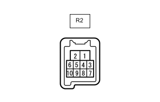
Disconnect the R2 front power window regulator motor assembly RH connector.
-
Measure the resistance and voltage according to the value(s) in the table below.
Terminal No. (Symbol) Wiring Color Terminal Description Condition Specified Condition R2-1 (GND) - Body ground B - Body ground Ground Always Below 1 Ω R2-2 (B) - Body ground L - Body ground Battery power supply Always 11 to 14 V -
Measure the pulse according to the value(s) in the table below.
Terminal No. (Symbol) Wiring Color Terminal Description Condition Specified Condition R2-9 (LIN) - Body ground W - Body ground LIN communication line Engine switch on (IG) Pulse generation
-
-
CHECK CERTIFICATION ECU (SMART KEY ECU ASSEMBLY)
-
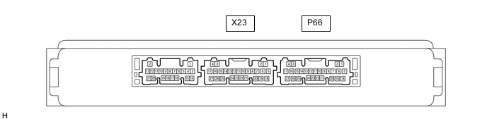
Disconnect the P66 certification ECU (smart key ECU assembly) connector.
-
Measure the resistance and voltage according to the value(s) in the table below.
Terminal No. (Symbol) Wiring Color Terminal Description Condition Specified Condition P66-4 (+B) - Body ground W - Body ground Battery power supply Always 11 to 14 V P66-18 (E) - Body ground W-B - Body ground Ground Always Below 1 Ω -
Measure the pulse according to the value(s) in the table below.
Terminal No. (Symbol) Wiring Color Terminal Description Condition Specified Condition P66-13 (LIN) - Body ground G - Body ground LIN communication line Engine switch on (IG) Pulse generation
-
-
CHECK STEERING LOCK ACTUATOR OR UPPER BRACKET ASSEMBLY
-
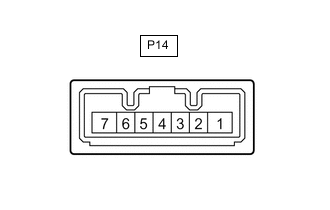
Disconnect the P14 steering lock actuator or upper bracket assembly connector.
-
Measure the resistance and voltage according to the value(s) in the table below.
Terminal No. (Symbol) Wiring Color Terminal Description Condition Specified Condition P14-1 (GND) - Body ground W-B - Body ground Ground Always Below 1 Ω P14-6 (IG2) - Body ground R - Body ground IG power supply Engine switch off Below 1 V Engine switch on (IG) 11 to 14 V P14-7 (B) - Body ground V - Body ground Battery power supply Always 11 to 14 V -
Measure the pulse according to the value(s) in the table below.
Terminal No. (Symbol) Wiring Color Terminal Description Condition Specified Condition P14-5 (LIN) - Body ground V - Body ground LIN communication line Engine switch on (IG) Pulse generation
-
-
CHECK ID CODE BOX (IMMOBILISER CODE ECU)
-
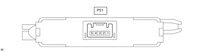
Disconnect the P51 ID code box (immobiliser code ECU) connector.
-
Measure the resistance and voltage according to the value(s) in the table below.
Terminal No. (Symbol) Wiring Color Terminal Description Condition Specified Condition P51-1 (+B) - Body ground GR - Body ground Battery power supply Always 11 to 14 V P51-5 (GND) - Body ground BR - Body ground Ground Always Below 1 Ω -
Measure the pulse according to the value(s) in the table below.
Terminal No. (Symbol) Wiring Color Terminal Description Condition Specified Condition P51-2 (LIN1) - Body ground L - Body ground LIN communication line Engine switch on (IG) Pulse generation
-
-
CHECK DOUBLE LOCK DOOR RELAY ASSEMBLY (w/Double Locking System)

-
Disconnect the P83 double lock door control relay assembly connector.
-
Measure the resistance and voltage according to the value(s) in the table below.
Terminal No. (Symbol) Wiring Color Terminal Description Condition Specified Condition P83-11 (CPUB) - Body ground LA-W - Body ground Battery power supply Always 11 to 14 V P83 -12 (+B) - Body ground LA-B - Body ground Battery power supply Always 11 to 14 V P83-7 (GND) - Body ground W-B - Body ground Ground Always Below 1 Ω -
Measure the pulse according to the value(s) in the table below.
Terminal No. (Symbol) Wiring Color Terminal Description Condition Specified Condition P83-9 (LIN) - Body ground LA-BE - Body ground LIN communication line Engine switch on (IG) Pulse generation
-