INTEGRATION RELAY(for Engine Room Side) INSTALLATION
PROCEDURE
-
INSTALL NO. 1 SEMICONDUCTOR POWER INTEGRATION ECU (for LHD)
-
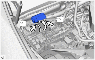
*a Power Supply Connector *b Lever Connector 
Connector Connect the power supply connector and lever connector to the No. 1 semiconductor power integration ECU.
Note
-
Do not touch the No. 1 semiconductor power integration ECU connector.
-
When pulling the No. 1 semiconductor power integration ECU, take care not to damage it.
-
Do not use a No. 1 semiconductor power integration ECU that has been dropped or subjected to a strong shock.
-
-
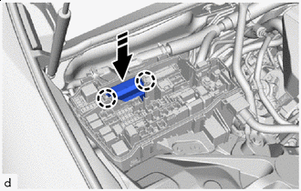

Install in this Direction Attach the claw to install the No. 1 semiconductor power integration ECU.
Note
When installing the No. 1 semiconductor power integration ECU, take care not to damage it.
-
-
INSTALL NO. 1 SEMICONDUCTOR POWER INTEGRATION ECU (for RHD)
-
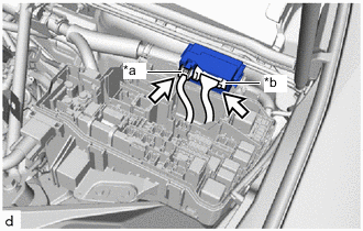
*a Power Supply Connector *b Lever Connector Connector Connect the power supply connector and lever connector to the No. 1 semiconductor power integration ECU.
Note
-
Do not touch the No. 1 semiconductor power integration ECU connector.
-
When pulling the No. 1 semiconductor power integration ECU, take care not to damage it.
-
Do not use a No. 1 semiconductor power integration ECU that has been dropped or subjected to a strong shock.
-
-
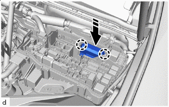
Install in this Direction Attach the claw to install the No. 1 semiconductor power integration ECU.
Note
When installing the No. 1 semiconductor power integration ECU, take care not to damage it.
-
-
INSTALL RELAY BLOCK UPPER COVER (for LHD)
-
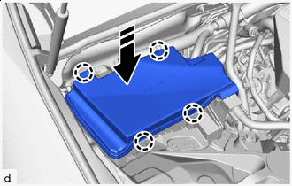
Install in this Direction Attach the claw to install the relay block upper cover.
-
-
INSTALL RELAY BLOCK UPPER COVER (for RHD)
-
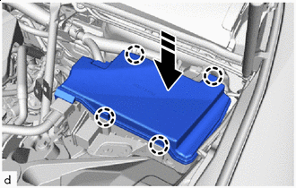
Install in this Direction Attach the claw to install the relay block upper cover.
-
-
CONNECT CABLE TO NEGATIVE BATTERY TERMINAL
Note
When disconnecting the cable, some systems need to be initialized after the cable is reconnected.
-
INSTALL NO. 2 DECK BOARD