INTEGRATION RELAY(for Engine Room Side) REMOVAL
CAUTION / NOTICE / HINT
The necessary procedures (adjustment, calibration, initialization, or registration) that must be performed after parts are removed, installed, or replaced during the No. 1 semiconductor power integration ECU removal/installation are shown below.
| Replacement part or procedure | Necessary procedures | Effects/Inoperative when not performed | Link |
|---|---|---|---|
| Disconnect cable from negative (-) battery terminal | Memorize steering angle neutral point | LKA/LDA system | |
| Pre-collision system | |||
| Parking assist monitor system | |||
| Steering sensor zero point calibration | Variable gear ratio steering system |
PROCEDURE
-
PRECAUTION
Note
After turning the engine switch off, waiting time may be required before disconnecting the cable from the negative (-) battery terminal. Therefore, make sure to read the disconnecting the cable from the negative (-) battery terminal notices before proceeding with work.
-
REMOVE NO. 2 DECK BOARD
-
DISCONNECT CABLE FROM NEGATIVE BATTERY TERMINAL
-
REMOVE RELAY BLOCK UPPER COVER (for LHD)
-
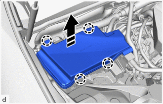

Remove in this Direction Detach the claw as shown in the illustration to remove the relay block upper cover.
-
-
REMOVE RELAY BLOCK UPPER COVER (for RHD)
-
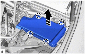
Remove in this Direction Detach the claw as shown in the illustration to remove the relay block upper cover.
-
-
REMOVE NO. 1 SEMICONDUCTOR POWER INTEGRATION ECU (for LHD)
-
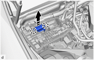
Remove in this Direction Using a screwdriver, detach the claw.
Tech Tips
Tape the screwdriver tip before use.
-
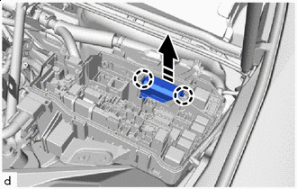
Pull up the No. 1 semiconductor power integration ECU.
Note
When pulling the No. 1 semiconductor power integration ECU, take care not to damage it.
-
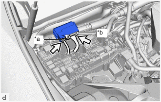
*a Power Supply Connector *b Lever Connector 
Connector Disconnect the power supply connector and then the lever connector and remove the No. 1 semiconductor power integration ECU.
Note
-
First disconnect the power supply connector.
-
Do not touch the No. 1 semiconductor power integration ECU connector.
-
When pulling the No. 1 semiconductor power integration ECU, take care not to damage it.
-
Do not use a No. 1 semiconductor power integration ECU that has been dropped or subjected to a strong shock.
-
-
-
REMOVE NO. 1 SEMICONDUCTOR POWER INTEGRATION ECU (for RHD)
-
Remove in this Direction Using a screwdriver, detach the claw.
Tech Tips
Tape the screwdriver tip before use.
-
Pull up the No. 1 semiconductor power integration ECU.
Note
When pulling the No. 1 semiconductor power integration ECU, take care not to damage it.
-
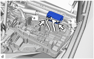
*a Power Supply Connector *b Lever Connector Connector Disconnect the power supply connector and then the lever connector and remove the No. 1 semiconductor power integration ECU.
Note
-
First disconnect the power supply connector.
-
Do not touch the No. 1 semiconductor power integration ECU connector.
-
When pulling the No. 1 semiconductor power integration ECU, take care not to damage it.
-
Do not use a No. 1 semiconductor power integration ECU that has been dropped or subjected to a strong shock.
-
-