MAIN BODY ECU REMOVAL
CAUTION / NOTICE / HINT
The necessary procedures (adjustment, calibration, initialization, or registration) that must be performed after parts are removed, installed, or replaced during the main body ECU (multiplex network body ECU) removal/installation are shown below.
| Replacement part or procedure | Necessary procedures | Effects/Inoperative when not performed | Link |
|---|---|---|---|
| Disconnect cable from negative (-) battery terminal | Memorize steering angle neutral point | LKA/LDA system | |
| Pre-collision system | |||
| Parking assist monitor system | |||
| Steering sensor zero point calibration | Variable gear ratio steering system | ||
| Replacement of main body ECU (multiplex network body ECU) | Code registration |
|
See Service Bulletin for the registration method. |
Tech Tips
-
Use the same procedure for RHD and LHD vehicles.
-
The procedure listed below is for LHD vehicles.
PROCEDURE
-
PRECAUTION
CAUTION:
Some of these service operations affect the SRS airbag system. Read the precautionary notices concerning the SRS airbag system before servicing.
Note
After turning the engine switch off, waiting time may be required before disconnecting the cable from the negative (-) battery terminal. Therefore, make sure to read the disconnecting the cable from the negative (-) battery terminal notices before proceeding with work.
-
REMOVE NO. 2 DECK BOARD
-
DISCONNECT CABLE FROM NEGATIVE BATTERY TERMINAL
CAUTION:
-
Wait at least 90 seconds after disconnecting the cable from the negative (-) battery terminal to disable the SRS system.
-
If the airbag deploys for any reason, it may cause a serious accident.
Note
When disconnecting the cable, some systems need to be initialized after the cable is reconnected.
-
-
REMOVE LOWER NO. 1 INSTRUMENT PANEL AIRBAG ASSEMBLY
-
REMOVE NO. 2 AIR DUCT
-
REMOVE HEATER TO REGISTER CENTER SUB DUCT
-
REMOVE NO. 1 SIDE TRIM BRACKET
-
REMOVE FRONT FLOOR CARPET ASSEMBLY LH
-

Remove in this Direction Detach the guide and remove a part of the front floor carpet assembly LH.
-
-
REMOVE NO. 3 INSTRUMENT PANEL TO COWL BRACE SUB-ASSEMBLY
-
REMOVE DRIVER SIDE JUNCTION BLOCK ASSEMBLY WITH MAIN BODY ECU
-
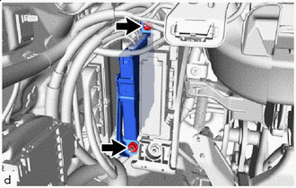

Nut Remove the 2 nuts and disconnect the ECU.
-
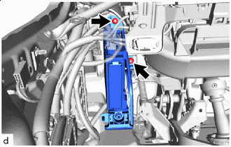
Nut Remove the 2 nuts and disconnect the driver side junction block assembly with main body ECU.
-
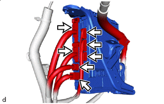

Connector Disconnect the 7 connectors.
-
Connector Detach the wire harness clamp.
-
Disconnect the 2 connectors and remove the driver side junction block assembly with main body ECU.
-
-
REMOVE MAIN BODY ECU (MULTIPLEX NETWORK BODY ECU)
-
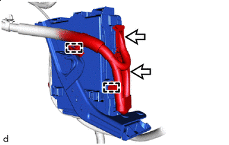
Nut Remove the nut.
-
Detach the claw and remove the wiring harness bracket.
-
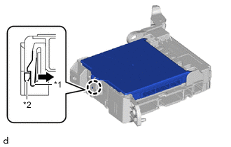
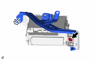
*1 Driver Side Junction Block Assembly *2 Main Body ECU (Multiplex Network Body ECU) Press the claw of the driver side junction block assembly as shown in the illustration to release the lock.
-
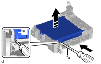
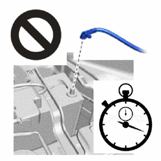
*a Protective Tape Remove in this Direction With the driver side junction block assembly lock released, insert a screwdriver with its tip wrapped with protective tape horizontally between the main body ECU (multiplex network body ECU) and driver side junction block assembly.
Note
-
Use a screwdriver with a diameter between 5.0 mm (0.197 in.) and 6.3 mm (0.248 in.) and a length of approximately 90 mm (3.54 in.).
-
Do not insert the screwdriver under the connector socket of the main body ECU (multiplex network body ECU).
-
-
Using the screwdriver, carefully raise the main body ECU (multiplex network body ECU) to the position where the connector becomes disconnected.
Note
-
Do not twist the screwdriver to raise the main body ECU (multiplex network body ECU).
-
Replace the driver side junction block assembly or the main body ECU (multiplex network body ECU) when the connector terminal, locking section or case is damaged or deformed.
-
-
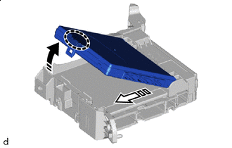

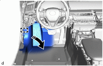
Place Hand Here Remove in this Direction (1) 
Remove in this Direction (2) Raise the main body ECU (multiplex network body ECU) as shown by the arrow (1), and then pull it out as shown by the arrow (2) in the illustration.
Note
-
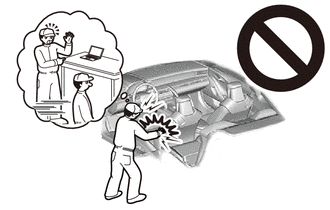
Do not touch the main body ECU (multiplex network body ECU) connector.
-
When removing the main body ECU (multiplex network body ECU), take care not to damage it.
-
Do not use a main body ECU (multiplex network body ECU) that has been dropped or subjected to a strong shock.
-
-