SUB BATTERY REMOVAL
CAUTION / NOTICE / HINT
The necessary procedures (adjustment, calibration, initialization or registration) that must be performed after parts are removed and installed, or replaced during sub battery module assembly removal/installation are shown below.
| Replacement Part or Procedure | Necessary Procedure | Effect/Inoperative when not Performed | Link |
|---|---|---|---|
| Disconnect cable from negative battery terminal | Memorize steering angle neutral point | LKA /LDA system | |
| Pre-collision system | |||
| Parking assist monitor system | |||
| Steering sensor zero point calibration | Variable gear ratio steering system |
PROCEDURE
-
REMOVE NO. 2 DECK BOARD
-
PRECAUTION
Note
After turning the engine switch off, waiting time may be required before disconnecting the cable from the negative (-) battery terminal. Therefore, make sure to read the disconnecting the cable from the negative (-) battery terminal notices before proceeding with work.
-
DISCONNECT CABLE FROM NEGATIVE BATTERY TERMINAL
Note
When disconnecting the cable, some systems need to be initialized after the cable is reconnected.
-
REMOVE NO. 1 DECK BOARD
-
REMOVE LUGGAGE COMPARTMENT TRIM COVER LH
-
REMOVE LUGGAGE COMPARTMENT TRIM COVER RH
-
REMOVE SIDE TRIM BOX
-
REMOVE REAR FLOOR FINISH PLATE
-
REMOVE LUGGAGE COMPARTMENT TRIM BOX
-
REMOVE NO. 1 LUGGAGE COMPARTMENT LIGHT ASSEMBLY
-
REMOVE FRONT LUGGAGE COMPARTMENT TRIM COVER
-
REMOVE INNER LUGGAGE COMPARTMENT TRIM COVER RH
-
REMOVE NO. 2 DECK BOARD BRACKET
-
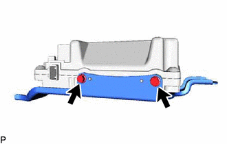
REMOVE CONNECTOR COVER
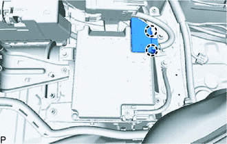
-
Detach the 2 claws and connector cover.
-
-
REMOVE SUB-BATTERY MODULE ASSEMBLY
-
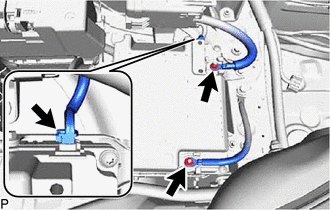
Loosen the 2 nuts and disconnect the 2 sub-battery terminals from the sub-battery module assembly.
-
Disconnect the connector from the sub-battery assembly with control.
-
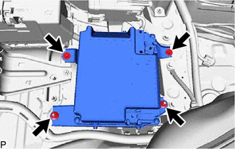
Loosen the 2 bolts and 2 nuts and disconnect the connector from the sub-battery module assembly.
-
-
REMOVE SUB-BATTERY BRACKET
-
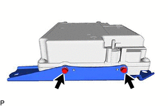
Loosen the 2 bolts and remove the sub-battery bracket (negative (-) terminal side) from the sub-battery module assembly.
-
Loosen the 2 bolts and remove the sub battery bracket (positive (+) terminal side) from the sub-battery module assembly.
-