SUB BATTERY SYSTEM, Diagnostic DTC:B22D4
| DTC Code | DTC Name |
|---|---|
| B22D4 | Sub Battery Module Protection Relay Temperature Sensor Circuit |
DESCRIPTION
| DTC No. | Detection Item | DTC Detection Condition | Trouble Area | Warning Indicate | Memory |
|---|---|---|---|---|---|
| B22D4 | Sub Battery Module Protection Relay Temperature Sensor Circuit | This DTC is stored when a malfunction is detected in the protection relay temperature sensor. (1 trip detection logic) |
Sub-battery module assembly | Comes on | DTC stored |
Tech Tips
The details of a DTC can be checked by using the DTC Sub Code of the freeze frame data that was recorded when the DTC was output.
| DTC Sub Code | Detail |
|---|---|
| "11" | Protection Relay FET Temperature1 is continuously 120°C (248°F) or less for 1 second |
| "12" | Protection Relay FET Temperature1 is continuously -40°C (-40°F) or less and Protection Relay FET Temperature2 is continuously 0°C (32°F) or more for 60 seconds |
| "13" | Protection Relay FET Temperature2 is continuously 120°C (248°F) or more for 1 second |
| "14" | Protection Relay FET Temperature2 is continuously -40°C (-40°F) or less and Protection Relay FET Temperature1 is continuously 0°C (32°F) or more for 60 seconds |
| "15" | Difference between Protection Relay FET Temperature1 and Protection Relay FET Temperature2 continuously exceeds the threshold for 1 second |
WIRING DIAGRAM
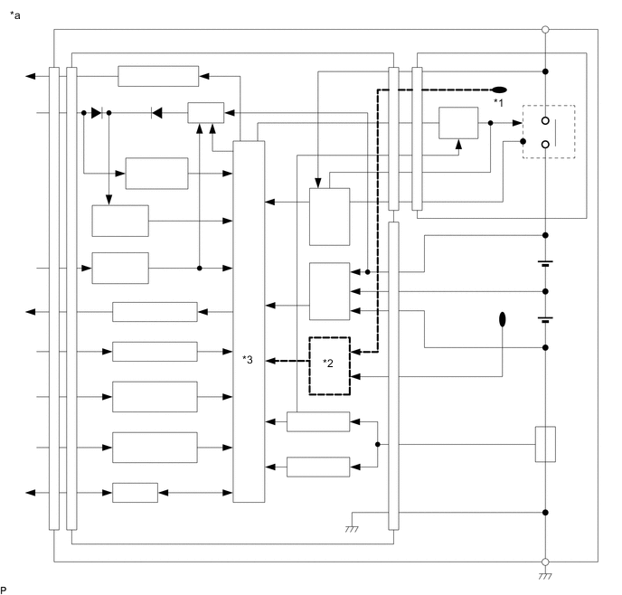
| *a | Sub-battery Module Assembly | - | - |
| *1 | Protection relay temperature sensor | *2 | Temperature detection circuit |
| *3 | CPU | - | - |
CAUTION / NOTICE / HINT
Tech Tips
Read freeze frame data using the GTS. Freeze frame data records the sub-battery module assembly condition when malfunctions are detected.
PROCEDURE
-
REPLACE SUB-BATTERY MODULE ASSEMBLY
-
Replace the sub-battery module assembly.
Result Proceed to NEXT
NEXT 
END
-