CLEARANCE WARNING ECU REMOVAL
CAUTION / NOTICE / HINT
The necessary procedures (adjustment, calibration, initialization or registration) that must be performed after parts are removed, installed or replaced during the clearance warning ECU assembly removal/installation are shown below.
| Replacement Part or Procedure | Necessary Procedures | Effects / Inoperative when not Performed | Link |
|---|---|---|---|
| Disconnect cable from negative (-) battery terminal | Memorize steering angle neutral point | LKA/LDA system | |
| Pre-collision system | |||
| Parking assist monitor system | |||
| Steering sensor zero point calibration | Variable gear ratio steering system | ||
| Front seat assembly RH (Only for removal and installation) | Initialize position control ECU | Front Power Seat Control System |
PROCEDURE
-
PRECAUTION
Note
After turning the engine switch off, waiting time may be required before disconnecting the cable from the negative (-) battery terminal. Therefore, make sure to read the disconnecting the cable from the negative (-) battery terminal notices before proceeding with work.
-
REMOVE FRONT SEAT ASSEMBLY RH
-
REMOVE FRONT DOOR SCUFF PLATE RH
-
REMOVE REAR SEAT CUSHION ASSEMBLY
-
REMOVE REAR SEAT CUSHION LOCK HOOK
-
REMOVE REAR SEAT SIDE GARNISH
-
REMOVE REAR SEATBACK COVER
-
REMOVE REAR SEATBACK ASSEMBLY RH
-
REMOVE OUTER LAP BELT ANCHOR COVER
-
REMOVE FRONT SEAT OUTER BELT ASSEMBLY RH(FLOOR ANCHOR)
-
REMOVE QUARTER INSIDE TRIM BOARD RH
-
REMOVE REAR SEAT INNER BELT ASSEMBLY RH
Tech Tips
Use the same procedure described for the rear No. 1 seat inner belt assembly LH.
-
REMOVE QUARTER TRIM PANEL ASSEMBLY RH
-
REMOVE CLEARANCE WARNING ECU ASSEMBLY
-
Disconnect the connector.
-
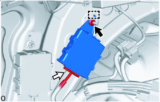

Nut 
Connector Remove the nut.
-
Detach the hook and remove the clearance warning ECU assembly.
-