BLIND SPOT MONITOR SYSTEM, Diagnostic DTC:C1AB3
| DTC Code | DTC Name |
|---|---|
| C1AB3 | Short to GND in Outer Mirror Indicator(Slave) |
DESCRIPTION
This DTC is stored when the blind spot monitor sensor LH detects a short to ground in the outer rear view mirror indicator LH.
| DTC No. | Detection Item | DTC Detection Condition | Trouble Area |
|---|---|---|---|
| C1AB3 | Short to GND in Outer Mirror Indicator(Slave) |
Both of the following conditions are met:
|
|
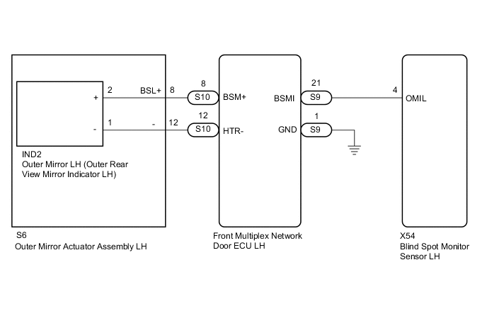
WIRING DIAGRAM
CAUTION / NOTICE / HINT
Note
When checking for DTCs, make sure that the blind spot monitor system is turned on.
PROCEDURE
-
CHECK DTC
-
Turn the engine switch off.
-
Turn the engine switch on (IG).
-
Recheck for DTCs and check if the same DTC is output again.
Body Electrical > Blind Spot Monitor Slave > Trouble CodesOK No DTCs are output. Result Proceed to OK NG
OK 
USE SIMULATION METHOD TO CHECK Click here
NG 
-
-
CHECK HARNESS AND CONNECTOR (BLIND SPOT MONITOR SENSOR LH - FRONT MULTIPLEX NETWORK DOOR ECU LH)
-
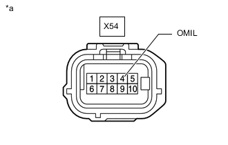
*a Front view of wire harness connector
(to Blind Spot Monitor Sensor LH)
Disconnect the X54 blind spot monitor sensor LH connector.
-
Disconnect the S9 front multiplex network door ECU LH connector.
-
Measure the resistance according to the value(s) in the table below.
Standard Resistance Tester Connection Condition Specified Condition X54-4 (OMIL) - Body ground Always 10 kΩ or higher Result Proceed to OK NG
NG
REPAIR OR REPLACE HARNESS OR CONNECTOR
OK
-
-
CHECK HARNESS AND CONNECTOR (FRONT MULTIPLEX NETWORK DOOR ECU LH - OUTER MIRROR ACTUATOR ASSEMBLY LH)
-
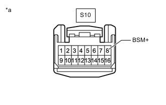
*a Front view of wire harness connector
(to Front Multiplex Network Door ECU LH)
Disconnect the S10 front multiplex network door ECU LH connector.
-
Disconnect the S6 outer mirror actuator assembly LH connector.
-
Measure the resistance according to the value(s) in the table below.
Standard Resistance Tester Connection Condition Specified Condition S10-8 (BSM+) - Body ground Always 10 kΩ or higher Result Proceed to OK NG
NG
REPAIR OR REPLACE HARNESS OR CONNECTOR
OK
-
-
INSPECT OUTER MIRROR ACTUATOR ASSEMBLY LH
-
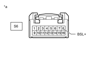
*a Component without harness connected
(Outer Mirror Actuator Assembly LH)
Disconnect the S6 outer mirror actuator assembly LH connector.
-
Disconnect the IND2 outer mirror LH (outer rear view mirror indicator LH) connector.
-
Measure the resistance according to the value(s) in the table below.
Standard Resistance Tester Connection Condition Specified Condition S6-8 (BSL+) - Body ground Always 10 kΩ or higher Result Proceed to OK NG
NG
REPLACE OUTER MIRROR ACTUATOR ASSEMBLY LH Click here
OK
-
-
INSPECT FRONT MULTIPLEX NETWORK DOOR ECU LH
-
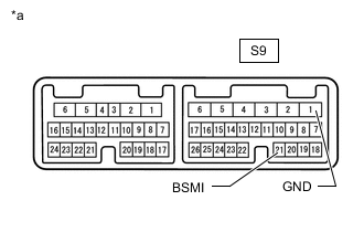
*a Component without harness connected
(Front Multiplex Network Door ECU LH)
Disconnect the front multiplex network door ECU LH connector.
-
Measure the resistance according to the value(s) in the table below.
Standard Resistance Tester Connection Condition Specified Condition S9-21 (BSMI) - S9-1 (GND) Always 10 kΩ or higher Result Proceed to OK NG
NG
REPLACE FRONT MULTIPLEX NETWORK DOOR ECU LH Click here
OK
-
-
INSPECT OUTER MIRROR LH (OUTER REAR VIEW MIRROR INDICATOR LH)
-
Remove the outer mirror LH (outer rear view mirror indicator LH).
-
Inspect the outer mirror LH (outer rear view mirror indicator LH).
Result Proceed to OK NG
OK
REPLACE BLIND SPOT MONITOR SENSOR LH Click here
NG
REPLACE OUTER MIRROR LH (OUTER REAR VIEW MIRROR INDICATOR LH) Click here
-