BLIND SPOT MONITOR SYSTEM, Diagnostic DTC:U0232
| DTC Code | DTC Name |
|---|---|
| U0232 | Lost Communication with Blind Spot Monitor Slave Module |
DESCRIPTION
This DTC is stored when the blind spot monitor sensor RH judges that there is a communication problem with the blind spot monitor sensor LH.
| DTC No. | Detection Item | DTC Detection Condition | Trouble Area |
|---|---|---|---|
| U0232 | Lost Communication with Blind Spot Monitor Slave Module | The blind spot monitor sensor (master) cannot receive signals from the blind spot monitor sensor (slave) |
|
WIRING DIAGRAM
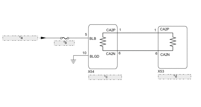
| *a | from LUG-IG1 NO.2 Relay |
| *b | LUG-IG1 NO.4 |
| *c | Blind Spot Monitor Sensor LH |
| *d | Blind Spot Monitor Sensor RH |
CAUTION / NOTICE / HINT
Note
-
When checking for DTCs, make sure that the blind spot monitor system is turned on.
-
Inspect the fuses for circuits related to this system before performing the following procedure.
-
Before measuring the resistance of the CAN bus, turn the engine switch off and leave the vehicle for 1 minute or more without operating the key or any switches, or opening or closing the doors. After that, disconnect the cable from the negative (-) battery terminal and leave the vehicle for 1 minute or more before measuring the resistance.
-
After turning the engine switch off, waiting time may be required before disconnecting the cable from the negative (-) battery terminal. Therefore, make sure to read the disconnecting the cable from the negative (-) battery terminal notices before proceeding with work.
Tech Tips
-
Operating the engine switch, any other switches or a door triggers related ECU and sensor communication on the CAN. This communication will cause the resistance value to change.
-
Even after DTCs are cleared, if a DTC is stored again after driving the vehicle for a while, the malfunction may be occurring due to vibration of the vehicle. In such a case, wiggling the ECUs or wire harness while performing the inspection below may help determine the cause of the malfunction.
PROCEDURE
-
CHECK CAN BUS MAIN WIRE
-
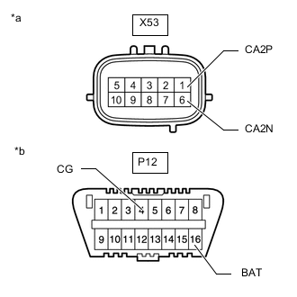
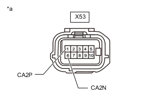
*a Component with harness connected
(Blind spot monitor sensor RH)
*b DLC3 Disconnect the cable from the negative (-) battery terminal.
-
Measure the resistance according to the value(s) in the table below.
Standard Resistance Tester Connection Condition Specified Condition Result X53-1 (CA2P) -X53-6 (CA2N) Cable disconnected from negative (-) battery terminal 54 to 69 Ω Below 54 Ω: Short circuit between bus lines 70 Ω or more: Open circuit in main bus lines X53-1(CA2P) - P12-4(CG) Cable disconnected from negative (-) battery terminal 200 Ω or higher Below 200 Ω: CA2P short to ground X53-6(CA2N) - P12-4(CG) Cable disconnected from negative (-) battery terminal 200 Ω or higher Below 200 Ω: CA2N short to ground X53-1(CA2P) - P12-16(BAT) Cable disconnected from negative (-) battery terminal 6 kΩ or higher Below 6 kΩ: CA2P +B short X53-6(CA2N) - P12-16(BAT) Cable disconnected from negative (-) battery terminal 6 kΩ or higher Below 6 kΩ: CA2N +B short Result Result Proceed to OK A Open circuit in CAN main bus lines B Short circuit between bus lines C
-
Short to ground
-
+B short
D -
B 
CHECK FOR OPEN IN CAN BUS MAIN WIRE (BLIND SPOT MONITOR SENSOR LH) Click here
C
CHECK FOR SHORT IN CAN BUS WIRES (BLIND SPOT MONITOR SENSOR LH) Click here
D
CHECK FOR SHORT IN CAN BUS WIRES (BLIND SPOT MONITOR SENSOR LH) Click here
A 
-
-
CHECK HARNESS AND CONNECTOR (BLIND SPOT MONITOR SENSOR LH - BODY GROUND)
-
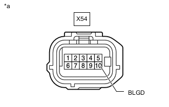
*a Front view of wire harness connector
(to Blind Spot Monitor Sensor LH)
Disconnect the blind spot monitor sensor LH connector.
-
Measure the resistance according to the value(s) in the table below.
Standard Resistance Tester Connection Condition Specified Condition X54-10 (BLGD) - Body ground Always Below 1 Ω Result Proceed to OK NG
NG 
REPAIR OR REPLACE HARNESS OR CONNECTOR
OK
-
-
CHECK HARNESS AND CONNECTOR (BLIND SPOT MONITOR SENSOR LH POWER SOURCE)
-
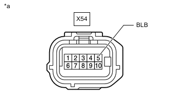
*a Front view of wire harness connector
(to Blind Spot Monitor Sensor LH)
Disconnect the blind spot monitor sensor LH connector.
-
Measure the voltage according to the value(s) in the table below.
Standard Voltage Tester Connection Switch Condition Specified Condition X54-5 (BLB) - Body ground Engine switch on (IG) 11 to 14 V X54-5 (BLB) - Body ground Engine switch off Below 1 V Result Proceed to OK NG
NG
REPAIR OR REPLACE HARNESS OR CONNECTOR
OK
-
-
CHECK DTC
-
Turn the engine switch off.
-
Turn the engine switch on (IG).
-
Check for DTCs.
Body Electrical > Blind Spot Monitor Master > Trouble CodesOK No DTCs are output. Result Proceed to OK NG
OK
USE SIMULATION METHOD TO CHECK Click here
NG
-
-
REPLACE BLIND SPOT MONITOR SENSOR LH
-
Replace the blind spot monitor sensor LH.
-
Clear the DTCs.
Body Electrical > Blind Spot Monitor Master > Clear DTCs -
Recheck for DTCs and check if the same DTC is output again.
Body Electrical > Blind Spot Monitor Master > Trouble CodesOK No DTCs are output. Result Proceed to OK NG
OK
END (BLIND SPOT MONITOR SENSOR LH WAS DEFECTIVE)
NG
REPLACE BLIND SPOT MONITOR SENSOR RH Click here
-
-
CHECK FOR OPEN IN CAN BUS MAIN WIRE (BLIND SPOT MONITOR SENSOR LH)
-
*a Front view of wire harness connector
(to blind spot monitor sensor LH)
Disconnect the cable from the negative (-) battery terminal.
-
Disconnect the blind spot monitor sensor LH connector.
-
Measure the resistance according to the value(s) in the table below.
Standard Resistance Tester Connection Condition Specified Condition X54-1 (CA2P) - X54-6 (CA2N) Cable disconnected from negative (-) battery terminal 108 to 132 Ω Result Proceed to OK NG
OK
REPLACE BLIND SPOT MONITOR SENSOR LH Click here
NG
-
-
CHECK FOR OPEN IN CAN BUS MAIN WIRE (BLIND SPOT MONITOR SENSOR RH)
-
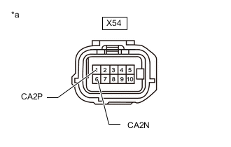
*a Front view of wire harness connector
(to blind spot monitor sensor RH)
Disconnect the cable from the negative (-) battery terminal.
-
Disconnect the blind spot monitor sensor RH connector.
-
Measure the resistance according to the value(s) in the table below.
Standard Resistance Tester Connection Condition Specified Condition X53-1 (CA2P) -X53-6 (CA2N) Cable disconnected from negative (-) battery terminal 108 to 132 Ω Result Proceed to OK NG
OK
REPLACE BLIND SPOT MONITOR SENSOR RH Click here
NG
REPAIR OR REPLACE CAN MAIN WIRE OR CONNECTOR (BLIND SPOT MONITOR SENSOR LH - BLIND SPOT MONITOR SENSOR RH)
-
-
CHECK FOR SHORT IN CAN BUS WIRES (BLIND SPOT MONITOR SENSOR LH)
-
*a Front view of wire harness connector
(to blind spot monitor sensor LH)
Disconnect the cable from the negative (-) battery terminal.
-
Disconnect the blind spot monitor sensor LH connector.
-
Measure the resistance according to the value(s) in the table below.
Standard Resistance Tester Connection Condition Specified Condition X54-1 (CA2P) - X54-6 (CA2N) Cable disconnected from negative (-) battery terminal 108 to 132 Ω Result Proceed to OK NG
OK
REPLACE BLIND SPOT MONITOR SENSOR LH Click here
NG
-
-
CHECK FOR SHORT IN CAN BUS WIRES (BLIND SPOT MONITOR SENSOR RH)
-
*a Front view of wire harness connector
(to blind spot monitor sensor RH)
Disconnect the cable from the negative (-) battery terminal.
-
Disconnect the blind spot monitor sensor RH connector.
-
Measure the resistance according to the value(s) in the table below.
Standard Resistance Tester Connection Condition Specified Condition X53-1 (CA2P) -X53-6 (CA2N) Cable disconnected from negative (-) battery terminal 108 to 132 Ω Result Proceed to OK NG
OK
REPLACE BLIND SPOT MONITOR SENSOR RH Click here
NG
REPAIR OR REPLACE CAN MAIN WIRE OR CONNECTOR (BLIND SPOT MONITOR SENSOR LH - BLIND SPOT MONITOR SENSOR RH)
-
-
CHECK FOR SHORT IN CAN BUS WIRES (BLIND SPOT MONITOR SENSOR LH)
-
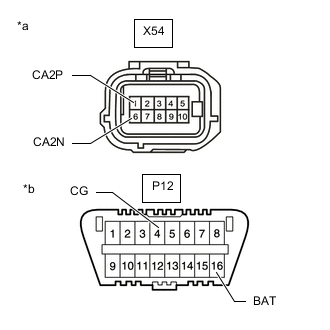
*a Front view of wire harness connector
(to blind spot monitor sensor LH)
*b DLC3 Disconnect the cable from the negative (-) battery terminal.
-
Disconnect the blind spot monitor sensor LH connector.
-
Measure the resistance according to the value(s) in the table below.
Standard Resistance Tester Connection Condition Specified Condition X54-1 (CA2P) - P12-4 (CG) Cable disconnected from negative (-) battery terminal 200 Ω or higher X54-6 (CA2N) - P12-4 (CG) Cable disconnected from negative (-) battery terminal 200 Ω or higher X54-1 (CA2P) - P12-16 (BAT) Cable disconnected from negative (-) battery terminal 6 kΩ or higher X54-6 (CA2N) - P12-16 (BAT) Cable disconnected from negative (-) battery terminal 6 kΩ or higher Result Proceed to OK NG
OK
REPLACE BLIND SPOT MONITOR SENSOR LH Click here
NG
-
-
CHECK FOR SHORT IN CAN BUS WIRES (BLIND SPOT MONITOR SENSOR RH)
-

*a Front view of wire harness connector
(to blind spot monitor sensor RH)
*b DLC3 Disconnect the cable from the negative (-) battery terminal.
-
Disconnect the blind spot monitor sensor RH connector.
-
Measure the resistance according to the value(s) in the table below.
Standard Resistance Tester Connection Condition Specified Condition X53-1 (CA2P) - P12-4 (CG) Cable disconnected from negative (-) battery terminal 200 Ω or higher X53-6 (CA2N) - P12-4 (CG) Cable disconnected from negative (-) battery terminal 200 Ω or higher X53-1 (CA2P) - P12-16 (BAT) Cable disconnected from negative (-) battery terminal 6 kΩ or higher X53-6 (CA2N) - P12-16 (BAT) Cable disconnected from negative (-) battery terminal 6 kΩ or higher Result Proceed to OK NG
OK
REPLACE BLIND SPOT MONITOR SENSOR RH Click here
NG
REPAIR OR REPLACE CAN MAIN WIRE OR CONNECTOR (BLIND SPOT MONITOR SENSOR LH - BLIND SPOT MONITOR SENSOR RH)
-