PERSONAL LIGHT INSPECTION
PROCEDURE
-
INSPECT MAP LIGHT SUB-ASSEMBLY
-
Inspect the map light sub-assembly.
-
Inspect the map light.
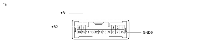
Apply battery voltage to the connector and check the light illumination condition.
*a Component without harness connected
(Map Light Sub-assembly)
- - OK If the result is not as specified, replace the map light sub-assembly.Battery Connection Switch Condition Specified Condition Positive (+) → 4 (+B1)
Positive (+) → 5 (+B2)
Negative (-) → 6 (GND9)
Map light switch LH ON Map light LH illuminates Map light switch RH ON Map light RH illuminates
Tech Tips
The map light switch is a capacitive touch switch. Therefore, the illumination turns on or off each time the lens around the light emitting area is touched.
-
Inspect the DOOR switch indicator.
Apply battery voltage to the connector and check the light illumination condition.
*a Component without harness connected
(Map Light Sub-assembly)
- - OK If the result is not as specified, replace the map light sub-assembly.Battery Connection Switch Condition Specified Condition Positive (+) → 4 (+B1)
Positive (+) → 5 (+B2)
Negative (-) → 6 (GND9)
DOOR switch ON DOOR switch indicator illuminates
-
Inspect the door courtesy light.
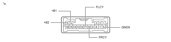
Apply battery voltage to the connector and check the light illumination condition.
*a Component without harness connected
(Map Light Sub-assembly)
- - OK If the result is not as specified, replace the map light sub-assembly.Battery Connection Switch Condition Specified Condition Positive (+) → 4 (+B1)
Positive (+) → 5 (+B2)
Negative (-) → 6 (GND9)
Negative (-) → 11 (FLCY)
DOOR switch ON Driver side light illuminates Positive (+) → 4 (+B1)
Positive (+) → 5 (+B2)
Negative (-) → 6 (GND9)
Negative (-) → 10 (FRCY)
Front passenger side light illuminates
-
Inspect the illumination.
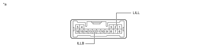
Apply battery voltage to the connector and check the light illumination condition.
*a Component without harness connected
(Map Light Sub-assembly)
- - OK If the result is not as specified, replace the map light sub-assembly.Battery Connection Switch Condition Specified Condition Positive (+) → 12 (ILLB)
Negative (-) → 2 (LILL)
Always Illuminates
-
-