LIGHTING SYSTEM Ambient Illumination Light Circuit
DESCRIPTION
The main body ECU (multiplex network body ECU) controls the ambient illumination lights.
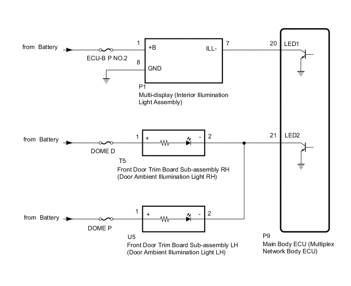
WIRING DIAGRAM
Figure 1. for LHD:
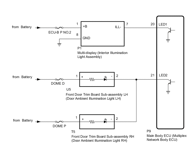
Figure 2. for RHD:
CAUTION / NOTICE / HINT
Note
-
Inspect the fuses for circuits related to this system before performing the following procedure.
-
Before replacing the main body ECU (multiplex network body ECU), refer to Service Bulletin.
PROCEDURE
-
CHECK AMBIENT ILLUMINATION LIGHTS
-
Check the illumination of each ambient illumination lights.
Result Result Proceed to Multi-display (interior illumination light assembly) does not illuminate. A Front door trim board sub-assembly (door ambient illumination light) does not illuminate. B
B 
PERFORM ACTIVE TEST USING GTS Click here
A 
-
-
PERFORM ACTIVE TEST USING GTS
-
Perform the Active Test according to the display on the GTS.
Body Electrical > Main Body > Active TestTester Display Measurement Item Control Range Diagnostic Note Interior Illumination Light1 Multi-display (interior illumination light assembly) ON or OFF Preconditions for using the Active Test to check dimmer controlled illumination:
-
Start the engine.
-
Shift lever is in any position other than P.
Body Electrical > Main Body > Active TestTester Display Interior Illumination Light1 OK Multi-display (interior illumination light assembly) turn on or off. Result Proceed to OK NG -
OK 
PROCEED TO NEXT SUSPECTED AREA SHOWN IN PROBLEM SYMPTOMS TABLE Click here
NG
-
-
CHECK HARNESS AND CONNECTOR (MULTI-DISPLAY [INTERIOR ILLUMINATION LIGHT ASSEMBLY] - BATTERY AND BODY GROUND)
-
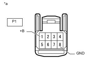
*a Front view of wire harness connector
(to Multi-display Assembly [Interior Illumination Light Assembly])
Disconnect the multi-display (interior illumination light assembly) connector.
-
Measure the voltage according to the value(s) in the table below.
Standard Voltage Tester Connection Condition Specified Condition P1-1 (+B) - Body ground Always 11 to 14 V -
Measure the resistance according to the value(s) in the table below.
Standard Resistance Tester Connection Condition Specified Condition P1-8 (GND) - Body ground Always Below 1 Ω Result Proceed to OK NG
NG
REPAIR OR REPLACE HARNESS OR CONNECTOR
OK
-
-
CHECK HARNESS AND CONNECTOR (MULTI-DISPLAY [INTERIOR ILLUMINATION LIGHT ASSEMBLY] - MAIN BODY ECU [MULTIPLEX NETWORK BODY ECU])
-
Disconnect the P1 multi-display (interior illumination light assembly) connector.
-
Disconnect the P9 main body ECU (multiplex network body ECU) connector.
-
Measure the resistance according to the value(s) in the table below.
Standard Resistance Tester Connection Condition Specified Condition P1-7 (ILL-) - P9-20 (LED1) Always Below 1 Ω P1-7 (ILL-) or P9-20 (LED1) - Body ground Always 10 kΩ or higher Result Proceed to OK NG
NG
REPAIR OR REPLACE HARNESS OR CONNECTOR
OK
-
-
CHECK MULTI-DISPLAY
-
Replace the multi-display.
-
Perform the Active Test according to the display on the GTS.
Body Electrical > Main Body > Active TestTester Display Measurement Item Control Range Diagnostic Note Interior Illumination Light1 Multi-display (interior illumination light assembly) ON or OFF Preconditions for using the Active Test to check dimmer controlled illumination:
-
Start the engine.
-
Shift lever is in any position other than P.
Body Electrical > Main Body > Active TestTester Display Interior Illumination Light1 OK Multi-display (interior illumination light assembly) turns on. Result Proceed to OK NG -
OK
END (MULTI-DISPLAY IS DEFECTIVE)
NG
REPLACE MAIN BODY ECU (MULTIPLEX NETWORK BODY ECU) Click here
-
-
PERFORM ACTIVE TEST USING GTS
-
Perform the Active Test according to the display on the GTS.
Body Electrical > Main Body > Active TestTester Display Measurement Item Control Range Diagnostic Note Interior Illumination Light2 Front door trim board sub-assembly (door ambient illumination light) ON or OFF Preconditions for using the Active Test to check dimmer controlled illumination:
-
Start the engine.
-
Shift lever is in any position other than P.
Body Electrical > Main Body > Active TestTester Display Interior Illumination Light2 OK Front door trim board sub-assembly (door ambient illumination light) turns on or off. Result Proceed to OK NG -
OK
PROCEED TO NEXT SUSPECTED AREA SHOWN IN PROBLEM SYMPTOMS TABLE Click here
NG
-
-
CHECK HARNESS AND CONNECTOR (FRONT DOOR TRIM BOARD SUB-ASSEMBLY - MAIN BODY ECU [MULTIPLEX NETWORK BODY ECU])
-
Disconnect the U5 front door trim board sub-assembly LH (door ambient illumination light LH) connector.
-
Disconnect the T5 front door trim board sub-assembly RH (door ambient illumination light RH) connector.
-
Disconnect the P9 main body ECU (multiplex network body ECU) connector.
-
Measure the resistance according to the value(s) in the table below.
Standard Resistance Tester Connection Condition Specified Condition U5-2 (-) - P9-21 (LED2) Always Below 1 Ω U5-2 (-) or P9-21 (LED2) - Body ground Always 10 kΩ or higher Result Proceed to OK NG
OK
REPLACE MAIN BODY ECU (MULTIPLEX NETWORK BODY ECU) Click here
NG
REPAIR OR REPLACE HARNESS OR CONNECTOR
-