LIGHTING SYSTEM Door Courtesy Switch Circuit
DESCRIPTION
The main body ECU (multiplex network body ECU) detects the condition of the courtesy light switch.
WIRING DIAGRAM
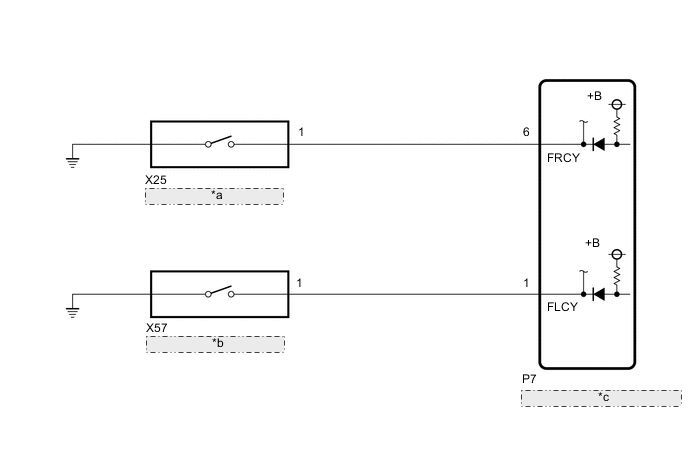
| *a | Courtesy Light Switch RH |
| *b | Courtesy Light Switch LH |
| *c | Main Body ECU (Multiplex Network Body ECU) |
CAUTION / NOTICE / HINT
Note
Before replacing the main body ECU (multiplex network body ECU), refer to Service Bulletin.
PROCEDURE
-
READ VALUE USING GTS
-
Read the Data List according to the display on the GTS.
Body Electrical > Main Body > Data ListTester Display Measurement Item Range Normal Condition Diagnostic Note FR Door Courtesy SW Courtesy light switch RH signal OFF or ON OFF: Front door RH closed
ON: Front door RH open
- FL Door Courtesy SW Courtesy light switch LH signal OFF or ON OFF: Front door LH closed
ON: Front door LH open
-
Body Electrical > Main Body > Data ListTester Display FR Door Courtesy SW FL Door Courtesy SW OK Normal conditions listed above are displayed. Result Result Proceed to OK A NG ("FR Door Courtesy SW" is abnormal) B NG ("FL Door Courtesy SW" is abnormal) C
A 
PROCEED TO NEXT SUSPECTED AREA SHOWN IN PROBLEM SYMPTOMS TABLE Click here
C 
INSPECT COURTESY LIGHT SWITCH LH Click here
B 
-
-
INSPECT COURTESY LIGHT SWITCH RH
-
Remove the courtesy light switch RH.
-
Inspect the courtesy light switch RH.
Result Proceed to OK NG
NG
REPLACE COURTESY LIGHT SWITCH RH Click here
OK
-
-
CHECK HARNESS AND CONNECTOR (COURTESY LIGHT SWITCH RH - MAIN BODY ECU [MULTIPLEX NETWORK BODY ECU])
-
Disconnect the X25 courtesy light switch RH connector.
-
Disconnect the P7 main body ECU (multiplex network body ECU) connector.
-
Measure the resistance according to the value(s) in the table below.
Standard Resistance Tester Connection Condition Specified Condition X25-1 - P7-6 (FRCY) Always Below 1 Ω X25-1 or P7-6 (FRCY) - Body ground Always 10 kΩ or higher Result Proceed to OK NG
OK
REPLACE MAIN BODY ECU (MULTIPLEX NETWORK BODY ECU) Click here
NG
REPAIR OR REPLACE HARNESS OR CONNECTOR
-
-
INSPECT COURTESY LIGHT SWITCH LH
-
Remove the courtesy light switch LH.
-
Inspect the courtesy light switch LH.
Result Proceed to OK NG
NG
REPLACE COURTESY LIGHT SWITCH LH Click here
OK
-
-
CHECK HARNESS AND CONNECTOR (COURTESY LIGHT SWITCH LH - MAIN BODY ECU [MULTIPLEX NETWORK BODY ECU])
-
Disconnect the X57 courtesy light switch LH connector.
-
Disconnect the P7 main body ECU (multiplex network body ECU) connector.
-
Measure the resistance according to the value(s) in the table below.
Standard Resistance Tester Connection Condition Specified Condition X57-1 - P7-1 (FLCY) Always Below 1 Ω X57-1 or P7-1 (FLCY) - Body ground Always 10 kΩ or higher Result Proceed to OK NG
OK
REPLACE MAIN BODY ECU (MULTIPLEX NETWORK BODY ECU) Click here
NG
REPAIR OR REPLACE HARNESS OR CONNECTOR
-