LIGHTING SYSTEM Interior Light Circuit
DESCRIPTION
The main body ECU (multiplex network body ECU) controls the operation of the map light sub-assembly (front dome light).
WIRING DIAGRAM
Figure 1. for LHD:
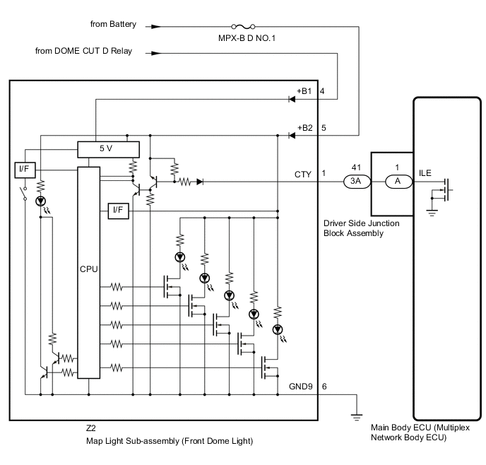
Figure 2. for RHD:

CAUTION / NOTICE / HINT
Note
-
Inspect the fuses and lights for circuits related to this system before performing the following procedure.
-
Before replacing the main body ECU (multiplex network body ECU), refer to Service Bulletin.
PROCEDURE
-
PERFORM ACTIVE TEST USING GTS
-
Perform the Active Test according to the display on the GTS.
Body Electrical > Main Body > Active TestTester Display Measurement Item Control Range Diagnostic Note Illuminated Entry System Map light sub-assembly (front dome light) illumination ON or OFF Perform the Active Test with DOOR switch in the map light sub-assembly turned on.
Body Electrical > Main Body > Active TestTester Display Illuminated Entry System OK Map light sub-assembly (front dome light) turn on. Result Proceed to OK NG
OK 
PROCEED TO NEXT SUSPECTED AREA SHOWN IN PROBLEM SYMPTOMS TABLE Click here
NG 
-
-
CHECK HARNESS AND CONNECTOR (MAP LIGHT SUB-ASSEMBLY - BATTERY)
-
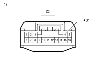
*a Front view of wire harness connector
(to Map Light Sub-assembly)
Disconnect the map light sub-assembly connector.
-
Enter the following menus: Body Electrical / Main Body / Active Test / Control the DOME CUT D relay.
Body Electrical > Main Body > Active TestTester Display Measurement Item Control Range Diagnostic Note Relay for Interior Light Auto Cut Function DOME CUT D relay ON or OFF ON: DOME CUT D relay off (interior lights turn off)
OFF: DOME CUT D relay on (interior lights turn on)
Body Electrical > Main Body > Active TestTester Display Relay for Interior Light Auto Cut Function -
Measure the voltage according to the value(s) in the table below.
Standard Voltage Tester Connection GTS Operation Specified Condition Z2-4 (+B1) - Body ground Active Test is not performed (OFF) 11 to 14 V Active Test is performed (ON) Below 1 V Result Proceed to OK NG
NG
REPAIR OR REPLACE HARNESS OR CONNECTOR
OK
-
-
CHECK HARNESS AND CONNECTOR (MAP LIGHT SUB-ASSEMBLY - BATTERY AND BODY GROUND)
-
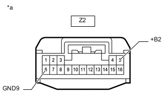
*a Front view of wire harness connector
(to Map Light Sub-assembly)
Disconnect the map light sub-assembly connector.
-
Measure the voltage according to the value(s) in the table below.
Standard Voltage Tester Connection Condition Specified Condition Z2-5 (+B2) - Body ground Always 11 to 14 V -
Measure the resistance according to the value(s) in the table below.
Standard Resistance Tester Connection Condition Specified Condition Z2-6 (GND9) - Body ground Always Below 1 Ω Result Result Proceed to OK (for LHD) A OK (for RHD) B NG C
B 
CHECK HARNESS AND CONNECTOR (DRIVER SIDE JUNCTION BLOCK ASSEMBLY- MAP LIGHT SUB-ASSEMBLY) Click here
C
REPAIR OR REPLACE HARNESS OR CONNECTOR
A
-
-
CHECK HARNESS AND CONNECTOR (DRIVER SIDE JUNCTION BLOCK ASSEMBLY- MAP LIGHT SUB-ASSEMBLY)
-
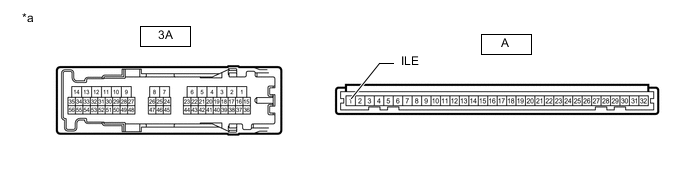
Disconnect the 3A driver side junction block assembly connector.
-
Disconnect the Z2 map light sub-assembly connector.
-
Measure the resistance according to the value(s) in the table below.
Standard Resistance Tester Connection Condition Specified Condition 3A-41 - Z2-1 (CTY) Always Below 1 Ω 3A-41 or Z2-1 (CTY) - Body ground Always 10 kΩ or higher Result Proceed to OK NG
NG
REPAIR OR REPLACE HARNESS OR CONNECTOR
OK
-
-
CHECK DRIVER SIDE JUNCTION BLOCK ASSEMBLY
-
Remove the driver side junction block assembly.
*a Component without harness connected
(Driver Side Junction Block Assembly)
- - -
Remove the main body ECU (multiplex network body ECU) from the driver side junction block assembly.
-
Measure the resistance according to the value(s) in the table below.
Standard Resistance Tester Connection Condition Specified Condition 3A-41 - A-1 (ILE) Always Below 1 Ω Result Proceed to OK NG
OK
REPLACE MAIN BODY ECU (MULTIPLEX NETWORK BODY ECU) Click here
NG
REPLACE DRIVER SIDE JUNCTION BLOCK ASSEMBLY Click here
-
-
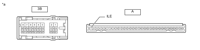
CHECK HARNESS AND CONNECTOR (DRIVER SIDE JUNCTION BLOCK ASSEMBLY- MAP LIGHT SUB-ASSEMBLY)
-
Disconnect the 3B driver side junction block assembly connector.
-
Disconnect the Z2 map light sub-assembly connector.
-
Measure the resistance according to the value(s) in the table below.
Standard Resistance Tester Connection Condition Specified Condition 3B-13 - Z2-1 (CTY) Always Below 1 Ω 3B-13 or Z2-1 (CTY) - Body ground Always 10 kΩ or higher Result Proceed to OK NG
NG
REPAIR OR REPLACE HARNESS OR CONNECTOR
OK
-
-
CHECK DRIVER SIDE JUNCTION BLOCK ASSEMBLY
-
Remove the driver side junction block assembly.
*a Component without harness connected
(Driver Side Junction Block Assembly)
- - -
Remove the main body ECU (multiplex network body ECU) from the driver side junction block assembly.
-
Measure the resistance according to the value(s) in the table below.
Standard Resistance Tester Connection Condition Specified Condition 3B-13 - A-1 (ILE) Always Below 1 Ω Result Proceed to OK NG
OK
REPLACE MAIN BODY ECU (MULTIPLEX NETWORK BODY ECU) Click here
NG
REPLACE DRIVER SIDE JUNCTION BLOCK ASSEMBLY Click here
-