LIGHTING SYSTEM TERMINALS OF ECU
-
CHECK DRIVER SIDE JUNCTION BLOCK ASSEMBLY AND MAIN BODY ECU (MULTIPLEX NETWORK BODY ECU)
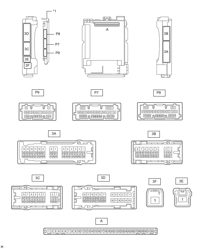
*1 Main Body ECU (Multiplex Network Body ECU) - -
-
Remove the main body ECU (multiplex network body ECU) from the driver side junction block assembly.
-
Connect the driver side junction block assembly.
-
Measure the voltage and resistance according to the value(s) in the table below.
Terminal No. (Symbol) Wiring Color Terminal Description Condition Specified Condition A-32 (IG) - Body ground Note - Body ground Ignition power supply Engine switch on (IG) 11 to 14 V Engine switch off Below 1 V A-31 (BECU) - Body ground Note - Body ground Battery power supply Always 11 to 14 V A-30 (ACC) - Body ground Note - Body ground ACC power supply Engine switch on (ACC) 11 to 14 V Engine switch off Below 1 V A-11 (GND1) - Body ground Note - Body ground Ground Always Below 1 Ω -
Install the main body ECU (multiplex network body ECU).
-
Measure the voltage and pulse according to the value(s) in the table below.
Terminal No. (Symbol) Wiring Color Terminal Description Condition Specified Condition P9-20 (LED1) - Body ground G - Body ground Multi-display (interior illumination light assembly) output Multi-display (interior illumination light assembly) off 11 to 14 V Multi-display (interior illumination light assembly) on Below 1 V P9-21 (LED2) - Body ground SB - Body ground Front door trim board sub-assembly (door ambient illumination light) output Front door trim board sub-assembly (door ambient illumination light) off 11 to 14 V Front door trim board sub-assembly (door ambient illumination light) on Below 1 V P7-1 (FLCY) - Body ground R - Body ground Courtesy light switch LH input Front door LH open Below 1 V Front door LH closed 4.7 to 5.3 V P7-6 (FRCY) - Body ground SB - Body ground Courtesy light switch RH input Front door RH open Below 1 V Front door LH closed 4.7 to 5.3 V 3D-27 (LGCY) - Body ground G - Body ground Luggage compartment door courtesy light switch input Luggage compartment door open Below 1 V Luggage compartment door closed 11 to 14 V P7-2 (FLCL) - Body ground V - Body ground Courtesy light switch LH output Courtesy light assembly LH off 11 to 14 V Courtesy light assembly LH on Below 1 V P7-3 (FRCL) - Body ground G - Body ground Ccourtesy light assembly RH output Courtesy light assembly RH off 11 to 14 V Courtesy light assembly RH on Below 1 V P7-20 (TCYL) - Body ground BR - Body ground No. 1 luggage compartment light assembly output No. 1 luggage compartment light assembly off 11 to 14 V No. 1 luggage compartment light assembly on Below 1 V 3D-31 (LSFL) - Body ground*1 P - Body ground Front door LH unlock detection switch input Front door LH locked Pulse generation Front door LH unlocked Below 1 V 3B-14 (LSFR) - Body ground*1 GR - Body ground Front door RH unlock detection switch input Front door RH locked Pulse generation Front door RH unlocked Below 1 V 3A-15 (LSFL) - Body ground*2 Y - Body ground Front door LH unlock detection switch input Front door LH locked Pulse generation Front door LH unlocked Below 1 V 3D-31 (LSFR) - Body ground*2 P - Body ground Front door RH unlock detection switch input Front door RH locked Pulse generation Front door RH unlocked Below 1 V 3A-36 (FSPT) - Body ground SB - Body ground No. 1 interior illumination light assembly LH (footwell light LH) output No. 1 interior illumination light assembly LH (footwell light LH) off 11 to 14 V No. 1 interior illumination light assembly LH (footwell light LH) on Below 1 V 3A-37 (FSPT) - Body ground GR - Body ground No. 1 interior illumination light assembly RH (footwell light RH) output No. 1 interior illumination light assembly RH (footwell light RH) off 11 to 14 V No. 1 interior illumination light assembly RH (footwell light RH) on Below 1 V 3B-5 - Body ground LA-W - Body ground Map light sub-assembly and vanity lights power supply DOME CUT D relay off 11 to 14 V DOME CUT D relay on Below 1 V 3A-41 (ILE) - Body ground*1 LG - Body ground Interior lights drive output Interior lights off (when operated by illuminated entry system) 11 to 14 V Interior lights on (when operated by illuminated entry system) Below 1 V 3B-13 (ILE) - Body ground*2 LG - Body ground Interior lights drive output Interior lights off (when operated by illuminated entry system) 11 to 14 V Interior lights on (when operated by illuminated entry system) Below 1 V P7-8 (ACAN) - Body ground Y - Body ground Dimming signal for other system (Output) Engine switch on (IG), automatic light control sensor covered by hand, and light control switch in AUTO position 11 to 14 V Engine switch on (IG), automatic light control sensor not covered by hand, and light control switch in AUTO position Below 1 V 3A-38 - Body ground*1 LA-G - Body ground Taillight signal Engine switch on (IG), light control switch TAIL 11 to 14 V Engine switch on (IG), light control switch off Below 1 V 3A-39 - Body ground*1 LA-R - Body ground Taillight signal Engine switch on (IG), light control switch TAIL 11 to 14 V Engine switch on (IG), light control switch off Below 1 V 3A-40 - Body ground*1 LA-L - Body ground Taillight signal Engine switch on (IG), light control switch TAIL 11 to 14 V Engine switch on (IG), light control switch off Below 1 V 3A-16 - Body ground*2 LA-R - Body ground Taillight signal Engine switch on (IG), light control switch TAIL 11 to 14 V Engine switch on (IG), light control switch off Below 1 V 3A-17 - Body ground*2 LA-L - Body ground Taillight signal Engine switch on (IG), light control switch TAIL 11 to 14 V Engine switch on (IG), light control switch off Below 1 V 3A-18 - Body ground*2 LA-G - Body ground Taillight signal Engine switch on (IG), light control switch TAIL 11 to 14 V Engine switch on (IG), light control switch off Below 1 V 3D-20 - Body ground LA-G - Body ground Taillight signal Engine switch on (IG), light control switch TAIL 11 to 14 V Engine switch on (IG), light control switch off Below 1 V *1: for LHD
*2: for RHD
-
-
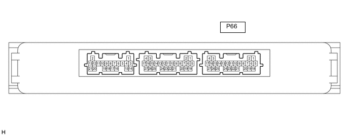
CHECK CERTIFICATION ECU (SMART KEY ECU ASSEMBLY)
-
Disconnect the P66 certification ECU (smart key ECU assembly) connector.
-
Measure the voltage and resistance according to the value(s) in the table below.
Terminal No. (Symbol) Wiring Color Terminal Description Condition Specified Condition P66-4 (+B) - Body ground W - Body ground Battery power supply Always 11 to 14 V P66-15 (CUTB)- Body ground P - Body ground Battery power supply Always 11 to 14 V P66-18 (E) - Body ground W-B - Body ground Ground Always Below 1 Ω -
Reconnect the P66 certification ECU (smart key ECU assembly) connector.
-
Measure the voltage according to the value(s) in the table below.
Terminal No. (Symbol) Wiring Color Terminal Description Condition Specified Condition P66-10 (SWIL) - P66-11 (AGND) B - L Engine switch illumination drive output Engine switch illumination on 11 to 14 V Engine switch illumination off Below 1 V
-
-
COMBINATION METER ASSEMBLY
@@-@@