REAR DISC BRAKE PAD INSTALLATION

CAUTION / NOTICE / HINT
Tech Tips
-
Use the same procedure for the RH and LH sides, except where indicated.
-
The following procedure is for the LH side.
PROCEDURE
-
INSTALL REAR DISC BRAKE ANTI-SQUEAL SHIM KIT
-
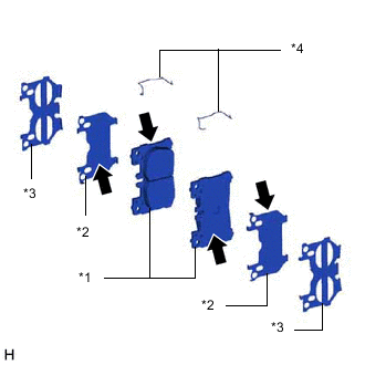
*1 Rear Disc Brake Pad *2 No. 1 Anti-Squeal Shim *3 No. 2 Anti-Squeal Shim *4 Inner Anti-Rattle Spring 
Disc Brake Grease Apply a light coat of disc brake grease to the anti-squeal shims and rear disc brake pads as shown in the illustration.
Note
-
Do not apply grease to the sides of the 2 No. 1 anti-squeal shims that contact the No. 2 anti-squeal shims.
-
There should be no oil or grease on the friction surfaces of the pads and the disc.
-
-
Install the inner anti-rattle spring to each rear disc brake pad.
-
Install the No. 1 anti-squeal shims and No. 2 anti-squeal shims to each rear disc brake pad.
-
-
INSTALL REAR DISC BRAKE PAD
CAUTION:
Be careful not to get pinched by the disc brake cylinder assembly or other parts when installing the rear disc brake pads.
-
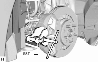
Using SST, push in the rear disc brake piston.
- SST
- 09719-77020
Note
-
Make sure the brake fluid does not overflow from the reservoir.
-
Do not forcibly push in the rear disc brake piston.
-
for RH side:
-
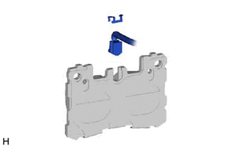
Install the pad wear indicator wire assembly RH to the rear disc brake pad (inner) with a new pad wear indicator retainer.
Note
When replacing the rear disc brake pads with new ones, make sure to replace the pad wear indicator wire assembly and pad wear indicator retainer at the same time.
-
-
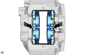
Install the 2 rear disc brake pads to the rear disc brake cylinder assembly LH.
Note
The rear disc brake pad with the pad wear indicator wire assembly must be installed to the inside position.
-
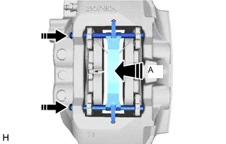
Install the anti-squeal spring between the 2 rear disc brake pads.
-
Install the No. 1 anti-rattle spring from the disc brake cylinder LH.
-
While pressing the area labeled A, install the 2 hole pins.
-
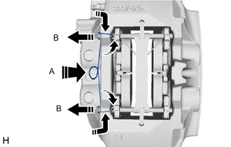
While pressing the area labeled A, slightly pull out the hole pin labeled B from the rear disc brake cylinder assembly LH, and install the pin hold clip.
-
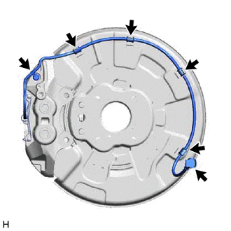
for RH side:
-
Attach the pad wear indicator wire assembly RH to the 4 clamps.
-
Connect the bleeder plug cap to the rear disc brake bleeder plug.
-
Connect the pad wear indicator wire connector to the rear speed sensor RH.
-
-
-
CONNECT BRAKE BOOSTER PUMP CONNECTOR
-
INSPECT BRAKE FLUID LEVEL IN RESERVOIR
-
INSTALL FRONT WHEEL