CAMSHAFT TIMING CONTROL MOTOR INSTALLATION
CAUTION / NOTICE / HINT
Tech Tips
Perform "Inspection After Repairs" after replacing the camshaft timing control motor with EDU assembly.
-
w/ Canister Pump Module:
-
w/o Canister Pump Module:
PROCEDURE
-
INSTALL CAMSHAFT TIMING CONTROL MOTOR WITH EDU ASSEMBLY RH
-
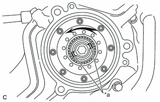
*a Index Slot Turn the camshaft timing gear assembly intermediate shaft index slot counterclockwise by hand, and set it to the maximum retard angle position.
Tech Tips
-
If a camshaft lobe is opening a valve, the intermediate shaft will be difficult to turn.
-
When the intermediate shaft index slot cannot be turned any farther it is set to the maximum retard angle.
-
-
Install a new O-ring to the timing chain cover assembly.
-
Align the joint of the camshaft timing control motor with EDU assembly RH and camshaft timing gear assembly intermediate shaft index slot.
-
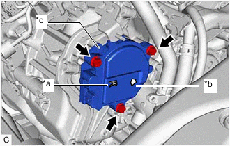
*a "R" Mark *b Arrow *c Knock Pin Install the camshaft timing control motor with EDU assembly RH to the timing chain cover assembly with the 3 bolts.
- Torque:
- 21 N*m { 214 kgf*cm, 15 ft.*lbf }
Note
-
Check that an "R" mark is printed on the label of the camshaft timing control motor with EDU assembly RH.
-
Make sure the contact surface of the camshaft timing control motor with EDU assembly RH (the surface that contacts the timing chain cover assembly) is free of foreign matter.
-
When installing the camshaft timing control motor with EDU assembly RH, do not use excessive force.
-
Install the camshaft timing control motor with EDU assembly RH with the arrow facing upward, as shown in the illustration.
-
Align the camshaft timing control motor with EDU assembly RH pin hole with the timing chain cover assembly knock pin when installing the camshaft timing control motor with EDU assembly RH.
-
If the camshaft timing control motor with EDU assembly RH has been struck or dropped, replace it.
-
Do not disassemble the camshaft timing control motor with EDU assembly RH. If disassembled, replace it.
-
-
INSTALL CAMSHAFT TIMING CONTROL MOTOR WITH EDU ASSEMBLY LH
-
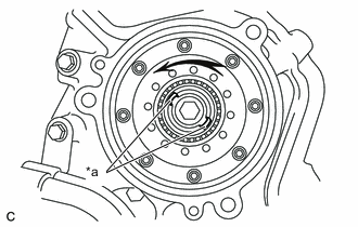
*a Index Slot Turn the camshaft timing gear assembly intermediate shaft index slot counterclockwise by hand, and set it to the maximum retard angle position.
Tech Tips
-
If a camshaft lobe is opening a valve, the intermediate shaft will be difficult to turn.
-
When the intermediate shaft index slot cannot be turned any farther it is set to the maximum retard angle.
-
-
Install a new O-ring to the timing chain cover assembly.
-
Align the joint of the camshaft timing control motor with EDU assembly LH and camshaft timing gear assembly intermediate shaft index slot.
-
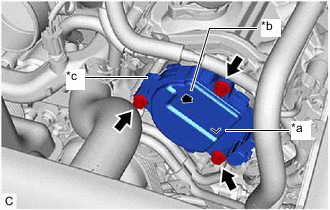
*a "L" Mark *b Arrow *c Knock Pin Install the camshaft timing control motor with EDU assembly LH to the timing chain cover assembly with the 3 bolts.
- Torque:
- 21 N*m { 214 kgf*cm, 15 ft.*lbf }
Note
-
Check that an "L" mark is printed on the label of the camshaft timing control motor with EDU assembly LH.
-
Make sure the contact surface of the camshaft timing control motor with EDU assembly LH (the surface that contacts the timing chain cover assembly) is free of foreign matter.
-
When installing the camshaft timing control motor with EDU assembly LH, do not use excessive force.
-
Install the camshaft timing control motor with EDU assembly LH with the arrow facing upward, as shown in the illustration.
-
Align the camshaft timing control motor with EDU assembly LH pin hole with the timing chain cover assembly knock pin when installing the camshaft timing control motor with EDU assembly LH.
-
If the camshaft timing control motor with EDU assembly LH has been struck or dropped, replace it.
-
Do not disassemble the camshaft timing control motor with EDU assembly LH. If disassembled, replace it.
-
-
CONNECT ENGINE WIRE
-
INSTALL NO. 2 INTAKE AIR CONNECTOR PIPE
-
INSTALL INTAKE AIR SOUND CREATOR
-
INSTALL INTAKE AIR CONNECTOR PIPE
-
INSTALL AIR CLEANER HOSE ASSEMBLY
-
CONNECT NO. 2 PCV HOSE
-
CONNECT NO. 3 PCV HOSE
-
INSTALL AIR CLEANER WITH ELEMENT ASSEMBLY RH
-
INSTALL AIR CLEANER WITH ELEMENT ASSEMBLY LH
-
INSTALL RADIATOR SUPPORT TO CROSS MEMBER BRACE SUB-ASSEMBLY LH
-
INSTALL RADIATOR SUPPORT TO CROSS MEMBER BRACE SUB-ASSEMBLY RH
-
INSTALL LOWER RADIATOR AIR DEFLECTOR
-
INSTALL RADIATOR SUPPORT TO FRAME SEAL LH
-
INSTALL RADIATOR SUPPORT TO FRAME SEAL RH
-
INSTALL V-BANK COVER SUB-ASSEMBLY
-
CONNECT CABLE TO NEGATIVE BATTERY TERMINAL
Note
When disconnecting the cable, some systems need to be initialized after the cable is reconnected.