SFI SYSTEM(w/o Canister Pump Module), Diagnostic DTC:P1651, P1654
| DTC Code | DTC Name |
|---|---|
| P1651 | Exhaust Exterior Valve 1 |
| P1654 | Exhaust Exterior Valve 2 |
DESCRIPTION
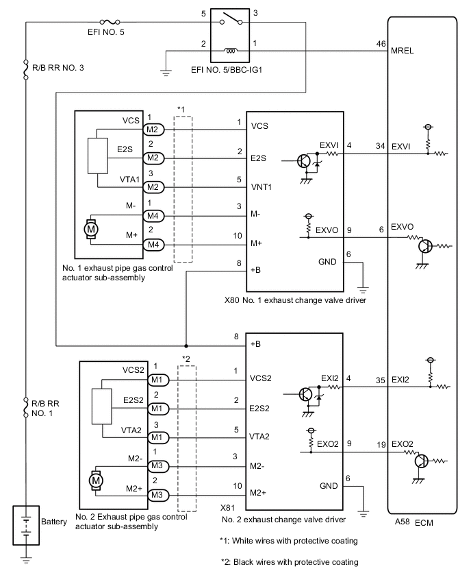
The dual exhaust system is made up of the exhaust tailpipe assembly (exhaust change valve), exhaust pipe gas control actuator sub-assembly (drive motor and opening angle sensor), exhaust change valve driver and ECM. According to changes in the gas path, the system ensures both quietness when the engine speed is low and exhaust tone when the engine speed is high.
The exhaust change valve driver receives drive signals from the ECM and operates the exhaust pipe gas control actuator sub-assembly drive motor and opens and closes the exhaust change valve.
The exhaust pipe gas control actuator sub-assembly position sensor detects the valve exhaust change valve opening angle and is fed back to the ECM as an exhaust valve operation status signal.
| DTC No. | Detection Item | DTC Detection Condition | Trouble Area | MIL | Memory |
|---|---|---|---|---|---|
| P1651 | Exhaust Exterior Valve 1 | Either of the following conditions is met for 10 seconds or more (1 trip detection logic):
|
|
Does not come on | DTC stored |
| P1654 | Exhaust Exterior Valve 2 | Either of the following conditions is met for 10 seconds or more (1 trip detection logic):
|
|
Does not come on | DTC stored |
MONITOR DESCRIPTION
If an exhaust pipe gas control actuator sub-assembly malfunction (drive motor, opening angle sensor) or an open or short in the exhaust change valve driver circuit is detected, a malfunction signal is sent to the ECM according to the status signal.
This DTC is stored when the malfunction signal sent from the exhaust valve control driver is received by the ECM.
CONFIRMATION DRIVING PATTERN
-
Connect the GTS to the DLC3.
-
Turn the engine switch on (IG).
-
Turn the GTS on.
-
Clear the DTCs (even if no DTCs are stored, perform the clear DTC procedure).
-
Turn the engine switch off and wait for at least 30 seconds.
-
Start the engine.
-
Idle the engine for 5 seconds.
-
Turn the GTS on.
-
Enter the following menus: Powertrain / Engine / Active Test / Control the Exhaust Exterior Valve Angle.
-
In the Active Test, wait for at least 20 seconds with the exhaust change valve opening position at 100%.
-
In the Active Test, wait for at least 20 seconds with the exhaust change valve opening position at 0%.
-
Enter the following menus: Powertrain / Engine / Trouble Codes.
-
Read the pending DTCs.
Tech Tips
-
If a pending DTC is output, the system is malfunctioning.
-
If a pending DTC is not output, perform the following procedure.
-
-
Enter the following menus: Powertrain / Engine / Utility / All Readiness.
-
Input the DTC: P1651 or P1654.
-
Check the DTC judgment result.
GTS Display Description NORMAL
-
DTC judgment completed
-
System normal
ABNORMAL
-
DTC judgment completed
-
System abnormal
INCOMPLETE
-
DTC judgment not completed
-
Perform driving pattern after confirming DTC enabling conditions
N/A
-
Unable to perform DTC judgment
-
Number of DTCs which do not fulfill DTC preconditions has reached ECU memory limit
Tech Tips
-
If the judgment result shows NORMAL, the system is normal.
-
If the judgment result shows ABNORMAL, the system has a malfunction.
-
If the judgment result shows INCOMPLETE or N/A, perform steps [F] through [H].
-
WIRING DIAGRAM
CAUTION / NOTICE / HINT
CAUTION:
Do no perform the Active Test with the exhaust pipe gas control actuator sub-assembly removed.
Tech Tips
-
Read freeze frame data using the GTS. The ECM records vehicle and driving condition information as freeze frame data the moment a DTC is stored. When troubleshooting, freeze frame data can help determine if the vehicle was moving or stationary, if the engine was warmed up or not, if the air fuel ratio was lean or rich, and other data from the time the malfunction occurred.
-
If DTC P1651 is output, check the white wires with protective coating on the exhaust pipe gas control actuator sub-assembly wiring system.
-
If DTC P1654 is output, check the black wires with protective coating on the exhaust pipe gas control actuator sub-assembly wiring system.
-
The connector for the exhaust pipe gas control actuator sub-assembly can be connected on either the left or right side.
When installing the wire harness after performing repairs, install it at the specified position.
-
Connect the No. 1 exhaust change valve driver to the No. 1 exhaust pipe gas control actuator sub-assembly connected to the white wires with protective coating
-
Connect the No. 2 exhaust change valve driver to the No. 2 exhaust pipe gas control actuator sub-assembly connected to the black wires with protective coating.
-
During troubleshooting, refer to the illustration below to check the colors of the profective coating of the exhaust pipe gas control actuator sub-assembly wire harness.
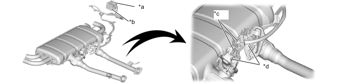
*a No. 1 exhaust change valve driver *b No. 2 exhaust change valve driver *c Wire harness (white or black wires with protective coating) *d Exhaust pipe gas control actuator sub-assembly
(No. 1: white wires with protective coating)
(No. 2: black wires with protective coating)
PROCEDURE
-
CHECK IF DTC OUTPUT RECURS
-
Switch connector M2, M4 and M1, M3 on the exhaust pipe gas control actuator sub-assembly.
-
Drive the vehicle in accordance with the driving pattern described in the Confirmation Driving Pattern.
-
Enter the following menus: Powertrain / Engine / Trouble Codes.
Powertrain > Engine > Trouble Codes -
Read the pending DTCs.
Result Result Proceed to DTCs do not change A DTCs change B
B 
CONFIRM PROBLEM SYMPTOMS Click here
A 
-
-
CHECK IF DTC OUTPUT RECURS
-
Switch connector X80 and X81 on the exhaust change valve driver.
Tech Tips
The wire harnesses are different lengths. Therefore, remove the exhaust change valve driver and change the position of the connnector.
-
Drive the vehicle in accordance with the driving pattern described in the Confirmation Driving Pattern.
-
Enter the following menus: Powertrain / Engine / Trouble Codes.
Powertrain > Engine > Trouble Codes -
Read the pending DTCs.
Result Result Proceed to DTCs do not change A DTCs change B
B 
REPLACE EXHAUST CHANGE VALVE DRIVER Click here
A
-
-
CHECK HARNESS AND CONNECTOR (EXHAUST CHANGE VALVE DRIVER - EXHAUST PIPE GAS CONTROL ACTUATOR SUB-ASSEMBLY)
-
Disconnect the exhaust change valve driver connector.
-
Disconnect the exhaust pipe gas control actuator sub-assembly connector.
-
Measure the resistance according to the value(s) in the table below.
Standard Resistance Tester Connection Condition Specified Condition X80-1(VCS) - M2-1(VCS) Always Below 1 Ω X80-2(E2S) - M2-2(E2S) Always Below 1 Ω X80-5(VNT1) - M2-3(VTA1) Always Below 1 Ω X80-3(M-) - M4-1(M-) Always Below 1 Ω X80-10(M+) - M4-2(M+) Always Below 1 Ω X81-1(VCS2) - M1-1(VCS2) Always Below 1 Ω X81-2(E2S2) - M1-2(E2S2) Always Below 1 Ω X81-5(VTA2) - M1-3(VTA2) Always Below 1 Ω X81-3(M2-) - M3-1(M2-) Always Below 1 Ω X81-10(M2+) - M3-2(M2+) Always Below 1 Ω X80-1(VCS) or M2-1(VCS) - Body ground and other terminals Always 10 kΩ or higher X80-2(E2S) or M2-2(E2S) - Body ground and other terminals Always 10 kΩ or higher X80-5(VNT1) or M2-3(VTA1) - Body ground and other terminals Always 10 kΩ or higher X80-3(M-) or M4-1(M-) - Body ground and other terminals Always 10 kΩ or higher X80-10(M+) or M4-2(M+) - Body ground and other terminals Always 10 kΩ or higher X81-1(VCS2) or M1-1(VCS2) - Body ground and other terminals Always 10 kΩ or higher X81-2(E2S2) or M1-2(E2S2) - Body ground and other terminals Always 10 kΩ or higher X81-5(VTA2) or M1-3(VTA2) - Body ground and other terminals Always 10 kΩ or higher X81-3(M2-) or M3-1(M2-) - Body ground and other terminals Always 10 kΩ or higher X81-10(M2+) or M3-2(M2+) - Body ground and other terminals Always 10 kΩ or higher Result Proceed to OK NG
NG
REPAIR OR REPLACE HARNESS OR CONNECTOR
OK
-
-
CHECK HARNESS AND CONNECTOR (EXHAUST CHANGE VALVE DRIVER - ECM)
-
Disconnect the exhaust change valve driver connector.
-
Disconnect the ECM connector.
-
Measure the resistance according to the value(s) in the table below.
Standard Resistance Tester Connection Condition Specified Condition A58-34(EXVI) - X80-4(VNTI) Always Below 1 Ω A58-6(EXVO) - X80-9(EXVO) Always Below 1 Ω A58-35(EXI2) - X81-4(EXI2) Always Below 1 Ω A58-19(EXO2) - X81-9(EXO2) Always Below 1 Ω A58-34(EXVI) or X80-4(EXVI) - Body ground and other terminals Always 10 kΩ or higher A58-6(EXVO) or X80-9(EXVO) - Body ground and other terminals Always 10 kΩ or higher A58-35(EXI2) or X81-4(EXI2) - Body ground and other terminals Always 10 kΩ or higher A58-19(EXO2) or X81-9(EXO2) - Body ground and other terminals Always 10 kΩ or higher Result Proceed to OK NG
OK
REPLACE ECM Click here
NG
REPAIR OR REPLACE HARNESS OR CONNECTOR
-
-
CONFIRM PROBLEM SYMPTOMS
-
Start and idle the engine.
-
Check the condition of the exhaust gas.
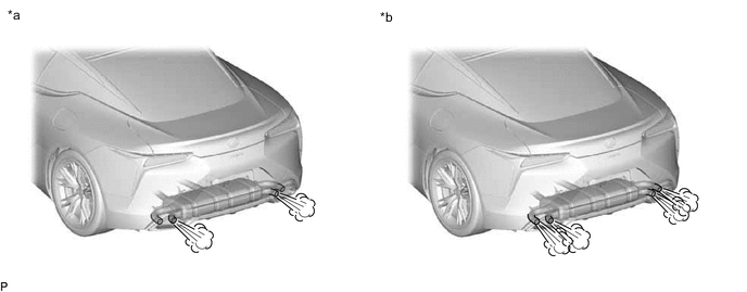
*1 Dual exhaust system *2 Quad exhaust system CAUTION:
Be careful of the exhaust gas, exhaust pipes and surrounding areas as they become extremely hot.
Result Result Proceed to Exhaust gas comes out of the dual exhaust system A Exhaust gas comes out of the quad exhaust system B
A
If a DTC is output while the valve is fully closed, the fully closed position of the valve may have become mechanically misaligned. When the fully closed position is misaligned, even if the exhaust pipe gas control actuator sub-assembly is replaced, parts may become damaged. Therefore, replace the exhaust tail pipe assembly (exhaust change valve) at the same time. REPLACE EXHAUST PIPE GAS CONTROL ACTUATOR SUB-ASSEMBLY AND EXHAUST TAILPIPE ASSEMBLY (EXHAUST CHANGE VALVE) Click here
B
-
-
INSPECT EXHAUST TAILPIPE ASSEMBLY (EXHAUST CHANGE VALVE)
-
Inspect the exhaust tailpipe assembly (exhaust change valve).
Tech Tips
If the result of the exhaust tail pipe assembly (exhaust change valve) inspection shows that the operation of the exhaust change valve is poor, replace the exhaust pipe gas control actuator sub-assembly and exhaust tail pipe assembly (exhaust change valve) at the same time.
Result Proceed to OK NG
OK
REPLACE EXHAUST PIPE GAS CONTROL ACTUATOR SUB-ASSEMBLY Click here
NG
REPLACE EXHAUST PIPE GAS CONTROL ACTUATOR SUB-ASSEMBLY AND EXHAUST TAILPIPE ASSEMBLY (EXHAUST CHANGE VALVE) Click here
-